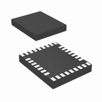
LP3950SL/NOPB National Semiconductor, LP3950SL/NOPB Datasheet - Page 21

LP3950SL/NOPB
Manufacturer Part Number
LP3950SL/NOPB
Description
IC LED DRVR WHITE BCKLGT 32-TSCP
Manufacturer
National Semiconductor
Series
PowerWise®r
Type
Backlight, White LED (I²C Interface)r
Datasheet
1.LP3950SLNOPB.pdf
(31 pages)
Specifications of LP3950SL/NOPB
Topology
PWM, Step-Up (Boost)
Number Of Outputs
6
Internal Driver
Yes
Type - Primary
Flash/Torch, LED Blinker, Light Management Unit (LMU)
Type - Secondary
RGB, White LED
Frequency
2MHz
Voltage - Supply
2.7 V ~ 2.9 V
Voltage - Output
5V
Mounting Type
Surface Mount
Package / Case
32-Laminate TCSP
Operating Temperature
-40°C ~ 85°C
Internal Switch(s)
Yes
Efficiency
90%
Led Driver Application
Mobile Phone Display Lighting, General LED Lighting
No. Of Outputs
6
Output Current
300mA
Output Voltage
5.3V
Input Voltage
3V To 7.2V
Rohs Compliant
Yes
Lead Free Status / RoHS Status
Lead free / RoHS Compliant
Current - Output / Channel
-
Other names
LP3950SL/CSP1
LP3950SLTR
LP3950SLTR
Zin
A
A
f
3 dB
IN_SINGLE
IN_DIFF
Audio Synchronization
CONTROL OF AUDIO SYNCHRONIZATION
The following table describes the controls required for audio
synchronization. Note that these controls are functional
when using serial interface (I
Also LP3950 audio synchronization functionality is illustrated
in Figure 18.
Symbol
EN_SYNC
SYNC_MODE
MODE_CTRL[1:0]
EN_AGC
GAIN_SEL[2:0]
INPUT_SEL[1:0]
SPEED_CTRL[1:0]
Input Impedance of AD1, AD2,
ASE pins
Audio Input Level Range
(peak-to-peak), Single Ended
Audio
Audio Input Level Range
(peak-to-peak), Differential
Audio
Crossover Frequencies (−3 dB)
Narrow Frequency Response
Wide Frequency Response
Parameter
2
C or SPI) for device control.
Audio synchronization enabled. Set EN_SYNC = 1 to enable audio synchronization or 0
to disable.
Synchronization mode selector. Set SYNC_MODE = 0 for amplitude synchronization. Set
SYNC_MODE = 1 for frequency synchronization.
See below: Mode control
Automatic gain control. Set EN_AGC = 1 to enable automatic control or 0 to disable.
When EN_AGC is disabled, the audio input signal gain value is defined by GAIN_SEL.
Input signal gain control. Gain has a range from 0 dB to 21 dB with 3 dB steps:
[000] ... 0 dB
[001] ... 3 dB
[010] ... 6 dB
[00] ... Single ended input signal, ASE.
[01] ... Differential input signal, AD1 and AD2.
[10] ... Stereo input or single ended and differential input signal.
Note: Sum of input signals divided by 2.
[11] ... No input
Please see Figure 15 for wiring.
Control for speed of the mapping. Sets the reaction speed (or "sampling rate") for the
audio input signal:
[00] ... FASTEST
[11] ... SLOW
In the amplitude mode f
(Continued)
Audio Synchronization Characteristics
Audio Synchronization Control
Low Pass
Band Pass
High Pass
Low Pass
Band Pass
High Pass
[011] ... 9 dB
[100] ... 12 dB
[101] ... 15 dB
[01] ... FAST
Conditions
MAX
= 3.8 Hz, in the frequency mode f
21
[110] ... 18 dB
[111] ... 21 dB
[10] ... MEDIUM
Min
200
0.1
0.1
1.0 and 1.5
2.0 and 3.0
Typ
500
MAX
0.5
2.0
1.0
4.0
= 7.6 Hz.
V
V
DDA
DDA
Max
−0.1
−0.1
www.national.com
Units
kHz
kΩ
V
V


