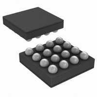
LM3554TME/NOPB National Semiconductor, LM3554TME/NOPB Datasheet - Page 17

LM3554TME/NOPB
Manufacturer Part Number
LM3554TME/NOPB
Description
IC LED DVR PHOTO FLASH 16-USMD
Manufacturer
National Semiconductor
Type
Photo Flash LED (I²C Interface)r
Datasheet
1.LM3554TMENOPB.pdf
(40 pages)
Specifications of LM3554TME/NOPB
Constant Current
Yes
Topology
High Side, Step-Up (Boost)
Number Of Outputs
2
Internal Driver
Yes
Type - Primary
Flash/Torch
Type - Secondary
White LED
Frequency
2MHz
Voltage - Supply
2.7 V ~ 5.5 V
Voltage - Output
5V
Mounting Type
Surface Mount
Package / Case
16-MicroSMD
Operating Temperature
-30°C ~ 85°C
Current - Output / Channel
600mA
Internal Switch(s)
Yes
Efficiency
90%
Led Driver Application
LED Backlighting, Portable Electronics
No. Of Outputs
2
Output Current
1.2A
Input Voltage
2.7V To 5.5V
Dimming Control Type
I2C
Rohs Compliant
Yes
Lead Free Status / RoHS Status
Lead free / RoHS Compliant
Other names
LM3554TMETR
MAXIMUM LOAD CURRENT (VOLTAGE MODE)
Assuming the power dissipation in the LM3554 and the am-
bient temperature are such that the device will not hit thermal
shutdown, the maximum load current as a function of I
Where η is efficiency and is found in the efficiency curves in
the Typical Performance Characteristics and
MAXIMUM OUTPUT POWER
Output power is limited by three things: the peak current limit,
the ambient temperature, and the maximum power dissipa-
tion in the package. If the LM3554’s die temperature is below
the absolute maximum rating of +125°C, the maximum output
power can be over 6W. However, any appreciable output cur-
rent will cause the internal power dissipation to increase and
Maximum Output Power (Voltage Output Mode)
In Voltage Output mode the total power dissipated in the
LM3554 can be approximated as:
The above formulas consider the average current through the
NFET and PFET. The actual power losses will be higher due
FIGURE 2. LM3554 Maximum Output Current
PEAK
is:
17
Figure 2
theoretical Efficiency at different input and output voltages
using the previous two equations for ΔI
current of 2.5A. This plot represents the theoretical maximum
output current (for the LM3554 in Voltage Output mode) that
the device can deliver just before hitting current limit.
therefore increase the die temperature. This can be addition-
ally compounded if the LED current sources are operating
while the device is in Voltage Output mode since the differ-
ence between V
sources. Any circuit configuration must ensure that the die
temperature remains below +125°C taking into account the
ambient temperature derating.
P
P
An approximate calculation of these losses gives:
to the RMS currents and the quiescent power into IN. These,
however, can give a decent approximation.
N
LED1
is the power lost in the NFET, P
, P
LED2
shows the theoretical maximum Output current vs
, and P
OUT
IND
and V
are the losses across the current sinks.
LED
is dropped across the current
30042008
P
is the PFET power loss,
L
and I
30042010
LOAD
www.national.com
with a peak


