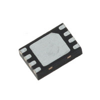
LDS8711 IXYS, LDS8711 Datasheet - Page 9

LDS8711
Manufacturer Part Number
LDS8711
Description
IC INTERFACE
Manufacturer
IXYS
Datasheet
1.LDS8711.pdf
(12 pages)
Specifications of LDS8711
Constant Current
*
Constant Voltage
*
Topology
*
Number Of Outputs
*
Internal Driver
*
Type - Primary
*
Type - Secondary
*
Frequency
*
Voltage - Supply
*
Voltage - Output
*
Mounting Type
Surface Mount
Package / Case
8-WFDFN Exposed Pad
Operating Temperature
*
Current - Output / Channel
*
Operating Supply Voltage
2.7 V to 5.5 V
Maximum Supply Current
3 mA
Maximum Operating Temperature
+ 85 C
Mounting Style
SMD/SMT
Minimum Operating Temperature
- 40 C
Lead Free Status / RoHS Status
Lead free / RoHS Compliant
Other names
LDS8711TR
LDS8711
We recommend C
achieve better efficiency and driver’s stability.
Recommended Layout
In active mode, the driver switches internally at a high
frequency. We recommend minimize trace length to
all external capacitors and inductor. The input and
output ceramic capacitors (X5R or X7R type) should
located as close to the device’ pins as possible to
prevent from EMI distribution
A ground plane should cover the area under the
driver IC as well as the bypass capacitors. Short
connection to ground on capacitors C
be implemented with the use of multiple via. A copper
area matching the TDFN exposed pad (PAD) must
be connected to the ground plane underneath. The
© 2010 IXYS Corp.
Characteristics subject to change without notice
OUT
in the range 1.0 – 2.2 µF to
IN
and C
OUT
can
9
use of multiple via improves the package heat
dissipation.
Figure 4. Recommended layout
Doc. No. 8711DS, Rev. N1.0


