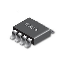
CY8CLEDAC02 Cypress Semiconductor Corp, CY8CLEDAC02 Datasheet - Page 7

CY8CLEDAC02
Manufacturer Part Number
CY8CLEDAC02
Description
IC CTLR AC-DC DIMMABLE LED 8SOIC
Manufacturer
Cypress Semiconductor Corp
Type
High Power, AC Input, Dimmabler
Datasheet
1.CY8CLEDAC02.pdf
(20 pages)
Specifications of CY8CLEDAC02
Package / Case
8-SOIC (3.9mm Width)
Voltage - Supply
8 V ~ 16 V
Frequency
200kHz
Operating Temperature
-40°C ~ 85°C
Number Of Outputs
1
Internal Switch(s)
No
Efficiency
85%
Topology
AC DC Offline Switcher
Operating Supply Voltage
- 0.3 V to 18 V
Maximum Supply Current
20 mA
Maximum Power Dissipation
526 mW
Maximum Operating Temperature
+ 85 C
Mounting Style
SMD/SMT
Minimum Operating Temperature
- 40 C
Operating Temperature (min)
-40C
Operating Temperature (max)
85C
Operating Temperature Classification
Industrial
Pin Count
8
Mounting
Surface Mount
Operating Supply Voltage (max)
18V
Lead Free Status / RoHS Status
Lead free / RoHS Compliant
Voltage - Output
-
Current - Output / Channel
-
Lead Free Status / Rohs Status
Lead free / RoHS Compliant
Available stocks
Company
Part Number
Manufacturer
Quantity
Price
Company:
Part Number:
CY8CLEDAC02
Manufacturer:
TI
Quantity:
900
Part Number:
CY8CLEDAC02
Manufacturer:
CYPRESS/赛普拉斯
Quantity:
20 000
Dimmer Tracking and Phase Measurement
Dimmer detection and tracking algorithms depend on accurate
measurement of the V
the second cycle of the dimmer discovery process and is then
latched for use. Using the measured V
calculations rather than a constant value enables automatic 50
or 60 Hz operation.
The phase measurement algorithm uses an internal counter that
starts counting when the rising threshold on V
counts input voltage samples until the voltage is above the
threshold. The counter is synchronized with the measured V
period and is restarted on every rising threshold (as shown in
Figure
The dimmer phase is calculated as:
Equation 1
The calculated D
When D
Document Number: 001-54879 Rev. *C
D
PHASE
6).
PHASE
BOOST
V
LED_EN
V
V
CROSS
IN
LED
is less than 0.2, D
PHASE
ZCD Threshold
t
t
IN
PERIOD
CROSS
is then used to generate a signal D
period. The period is measured during
V
V
ZCD Threshold
CROSS
INA
t
RATIO
CROSS
t0
Figure 6. Dimmer Tracking and Phase Measurement
t
PERIOD
IN
is set to 0.02 and when
period in subsequent
IN
is exceeded and
Figure 5. Dimmer Detection
RATIO
t
CROSS
IN
.
D
cases D
Equation 2
where K1 and K2 are constants with values 1.63 and 0.3 respec-
tively.
The output power to the LED load is modulated by D
D
when D
load.
The voltage at the I
output LED current can be set at a nominal value and modulated
using the following equation:
Equation 3
This equation provides a mapping from the measured dimmer
phase to actual light output.
t
PERIOD
PHASE
RATIO
V
D
ISENSE
RATIO
is 1, 100 percent power is provided to the LED load, and
RATIO
RATIO
is greater than 0.8, D
of 0.1, 10 percent power is provided to the LED
is set using the following equation:
V
D
I
SENSE
PHASE
SENSE
pin V
(
NOM
RATIO
K
ISENSE
)
1
is set to 1.0. For all other
CY8CLEDAC02
, which modulates the
D
K
RATIO
2
Page 7 of 20
RATIO
. When
[+] Feedback


