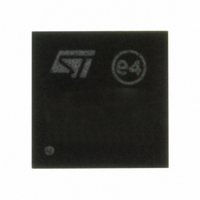
PM6600 STMicroelectronics, PM6600 Datasheet - Page 35

PM6600
Manufacturer Part Number
PM6600
Description
IC LED DRIVR WHT BCKLT 24-VFQFPN
Manufacturer
STMicroelectronics
Type
Backlight, White LEDr
Datasheet
1.PM6600TR.pdf
(60 pages)
Specifications of PM6600
Topology
PWM, Step-Up (Boost)
Number Of Outputs
6
Internal Driver
Yes
Type - Primary
Backlight
Type - Secondary
White LED
Frequency
200kHz ~ 1MHz
Voltage - Supply
4.7 V ~ 28 V
Voltage - Output
36V
Mounting Type
Surface Mount
Package / Case
24-VFQFN, 24-VFQFPN
Operating Temperature
-40°C ~ 85°C
Current - Output / Channel
32mA
Internal Switch(s)
Yes
Number Of Segments
60
Operating Supply Voltage
4.7 V to 28 V
Maximum Power Dissipation
2.3 W
Maximum Operating Temperature
+ 85 C
Mounting Style
SMD/SMT
Minimum Operating Temperature
- 40 C
For Use With
497-8414 - BOARD EVAL BASED ON PM6600
Lead Free Status / RoHS Status
Lead free / RoHS Compliant
Efficiency
-
Lead Free Status / Rohs Status
Details
Available stocks
Company
Part Number
Manufacturer
Quantity
Price
Company:
Part Number:
PM6600
Manufacturer:
FUJITSU
Quantity:
2 402
Company:
Part Number:
PM6600TR
Manufacturer:
ST
Quantity:
11 965
Company:
Part Number:
PM6600TR
Manufacturer:
st
Quantity:
5 145
PM6600
7.6
7.7
Boost current limit
The design of the external components, especially the inductor and the flywheel diode, must
be optimized in terms of size relying on the programmable peak current limit. The PM6600
improves the reliability of the final application giving the way to limit the maximum current
flowing into the critical components. A simple resistor connected between the BILIM pin and
ground sets the desired value. The voltage at the BILIM pin is internally fixed to 1.2 V and
the current limit is proportional to the current flowing through the setting resistor, according
to the following equation:
Equation 16
where
The maximum allowed current limit is 5 A, resulting in a minimum setting resistor
R
current limitation works by clamping the COMP pin voltage proportionally to R
inductor current is limited to the above threshold decreased by the slope compensation
contribution.
In a boost converter the r.m.s. current through the internal MOSFET depends on both the
input and output voltages, according to equations 15a (DCM) and 15b (CCM).
Equation 17 a
Equation 17 b
Enable function
The PM6600 is enabled by the EN pin. This pin is active high and, when forced to SGND,
the device is turned off. This pin is connected to a permanently active 2 μA current source;
when sudden device turn-on at power-up is required, this pin must be left floating or
connected to a delay capacitor. When turned off, the PM6600 quickly discharges the Soft-
Start capacitor and turns off the power-MOSFET, the current generators and the LDO. The
power consumption is thus reduced to 20 μA only.
The proper startup sequence is DIM ' VIN ' EN, or VIN ' DIM ' EN. If the dimming signal is
applied after the EN pin, the device will not perform the soft-start again, in fact it will start
switching with the maximum current limit in order to recover the output voltage.
In applications where the dimming signal is used to turn on and off the device, the EN pin
can be connected to the DIM pin as shown in
BILIM
> 120 kΩ. The maximum guaranteed RMS current in the power switch is 2 Arms. The
K
B
=
6
7 .
⋅
10
I
MOS
5
V
,
rms
±
15
=
%
I
OUT
Doc ID 14248 Rev 7
.
⎛
⎜
⎜
⎝
(
1
I
I
MOS
BOOST
−
D
D
,
rms
)
2
,
PEAK
+
=
12
1
F
V
Figure 52
SW
IN
⎛
⎜
⎜
⎝
=
I
OUT
R
⋅
⋅
D
K
L
BILIM
V
B
OUT
⋅
f
D
3
SW
.
⋅
L
⎞
⎟
⎟
⎠
2
(
D
(
1
−
Operation description
D
)
)
3
⎞
⎟
⎟
⎠
BILIM
. Peak
35/60


