L6202 STMicroelectronics, L6202 Datasheet - Page 3
L6202
Manufacturer Part Number
L6202
Description
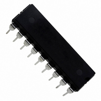
IC DRIVER FULL BRIDGE 18PWRDIP
Manufacturer
STMicroelectronics
Type
H Bridger
Specifications of L6202
Input Type
Non-Inverting
Number Of Outputs
2
On-state Resistance
300 mOhm
Current - Output / Channel
1.5A
Current - Peak Output
5A
Voltage - Supply
12 V ~ 48 V
Operating Temperature
-40°C ~ 150°C
Mounting Type
Through Hole
Package / Case
18-DIP (0.300", 7.62mm)
Operating Supply Voltage
12 V to 48 V
Supply Current
0.015 A
Mounting Style
Through Hole
Current, Output, High Level
2 mA
Package Type
SO20
Power Dissipation
1.3 W
Temperature, Operating, Maximum
150 °C
Temperature, Operating, Minimum
-40 °C
Voltage, Input, High Level
7 V (Max.)
Voltage, Input, Low Level
0.8 V (Max.)
Voltage, Supply
36 V (Typ.)
Lead Free Status / RoHS Status
Lead free / RoHS Compliant
Other names
497-1420-5
Available stocks
Company
Part Number
Manufacturer
Quantity
Price
Company:

Part Number:
L6202
Manufacturer:
STMicroelectronics
Quantity:
1 900
Part Number:
L6202
Manufacturer:
ST
Quantity:
20 000


L6201 - L6202 - L6203
THERMAL DATA
(*) Mounted on aluminium substrate.
ELECTRICAL CHARACTERISTICS (Refer to the Test Circuits; T
otherwise specified).
TRANSISTORS
SOURCE DRAIN DIODE
LOGIC LEVELS
4/20
V
V
Symbol
Rt
Rt
OFF
ON
Rt
I
I
IN H
IN H
IN L
IN L
Symbol
V
h j-case
h j-amb
h j-pins
V
DS(ON)
I
I
R
V
V
REF
DSS
, V
, V
, I
, I
V
T
sens
T
t
t
I
f
DS
ref
s
c
sd
rr
fr
d
s
j
EN L
EN H
EN L
EN H
Thermal Resistance Junction-pins
Thermal Resistance Junction Case
Thermal Resistance Junction-ambient
Supply Voltage
Reference Voltage
Output Current
Quiescent Supply Current
Commutation Frequency (*)
Thermal Shutdown
Dead Time Protection
Leakage Current
On Resistance
Drain Source Voltage
Sensing Voltage
Forward ON Voltage
Reverse Recovery Time
Forward Recovery Time
Input Low Voltage
Input High Voltage
Input Low Current
Input High Current
Parameter
Parameter
I
EN = H V
EN = H V
EN = L ( Fig. 1,2,3)
Fig. 11 V
Fig. 4,5
Fig. 9
I
I
I
Fig. 6a and b
I
I
I
L
I
I
I
V
V
dif
dt
REF
DS
DS
DS
SD
SD
SD
F
F
F
IN
IN
= 1A
= 1.2A
= 3A
max.
max.
, V
, V
max
= 25 A/ s
= 1A
= 1.2A
= 3A
= 1A
= 1.2A L6202
= 3A
= 2mA
EN
EN
Test Conditions
= L
= H
s
IN
IN
= 52 V
L6201
L6201
L6201PS/03 EN =
= L
= H
15
85
–
L6201PS/0
L6201PS
EN = L
EN = L
L6201
L6202
L6203
I
13 (*)
L
L6201
L6202
j
3
–
–
= 0
= 25 C, V
Value
– 0.3
Min.
L6202
– 1
12
2
12
60
–
S
= 42V, V
1.35(**)
0.9 (**)
0.9 (**)
Typ.
0.36
13.5
150
100
300
200
0.3
0.3
0.9
36
10
10
30
30
8
L6203
35
–
3
sens
Max.
0.55
100
–10
0.8
48
15
15
15
2
1
4
7
= 0, unless
Unit
C/W
Unit
KHz
mA
mA
mA
mA
mA
ns
ns
ns
V
V
V
V
V
V
V
V
V
V
V
C
A
A
Related parts for L6202
Image
Part Number
Description
Manufacturer
Datasheet
Request
R

Part Number:
Description:
STMicroelectronics [RIPPLE-CARRY BINARY COUNTER/DIVIDERS]
Manufacturer:
STMicroelectronics
Datasheet:
Part Number:
Description:
STMicroelectronics [LIQUID-CRYSTAL DISPLAY DRIVERS]
Manufacturer:
STMicroelectronics
Datasheet:

Part Number:
Description:
BOARD EVAL FOR MEMS SENSORS
Manufacturer:
STMicroelectronics
Datasheet:
Part Number:
Description:
NPN TRANSISTOR POWER MODULE
Manufacturer:
STMicroelectronics
Datasheet:
Part Number:
Description:
TURBOSWITCH ULTRA-FAST HIGH VOLTAGE DIODE
Manufacturer:
STMicroelectronics
Datasheet:
Part Number:
Description:
Manufacturer:
STMicroelectronics
Datasheet:
Part Number:
Description:
DIODE / SCR MODULE
Manufacturer:
STMicroelectronics
Datasheet:
Part Number:
Description:
DIODE / SCR MODULE
Manufacturer:
STMicroelectronics
Datasheet:
Part Number:
Description:
Search -----> STE16N100
Manufacturer:
STMicroelectronics
Datasheet:
Part Number:
Description:
Search ---> STE53NA50
Manufacturer:
STMicroelectronics
Datasheet:
Part Number:
Description:
NPN Transistor Power Module
Manufacturer:
STMicroelectronics
Datasheet:
Part Number:
Description:
DIODE / SCR MODULE
Manufacturer:
STMicroelectronics
Datasheet: