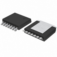
BD6231HFP-TR Rohm Semiconductor, BD6231HFP-TR Datasheet - Page 12

BD6231HFP-TR
Manufacturer Part Number
BD6231HFP-TR
Description
IC H-BRIDGE DVR 36V 1CH 1A HRP7
Manufacturer
Rohm Semiconductor
Series
-r
Type
Half Bridge Driverr
Datasheet
1.BD6230HFP-TR.pdf
(17 pages)
Specifications of BD6231HFP-TR
Applications
DC Motor Driver
Number Of Outputs
1
Current - Output
1A
Voltage - Supply
6 V ~ 32 V
Operating Temperature
-40°C ~ 85°C
Mounting Type
Surface Mount
Package / Case
HRP-7
Evaluation Tools
-
Voltage - Load
-
Product
H-Bridge Drivers
Supply Voltage (max)
36 V
Supply Voltage (min)
6 V
Supply Current
1.3 mA
Maximum Power Dissipation
1.4 W
Maximum Operating Temperature
+ 85 C
Mounting Style
SMD/SMT
Bridge Type
H-bridge
Minimum Operating Temperature
- 40 C
Number Of Drivers
1
Output Current
1 A
Operating Supply Voltage
6 V to 32 V
Lead Free Status / RoHS Status
Lead free / RoHS Compliant
Voltage - Load
-
Lead Free Status / Rohs Status
Lead free / RoHS Compliant
Available stocks
Company
Part Number
Manufacturer
Quantity
Price
Company:
Part Number:
BD6231HFP-TR
Manufacturer:
ROHM Semiconductor
Quantity:
3 984
Company:
Part Number:
BD6231HFP-TR
Manufacturer:
ROHM
Quantity:
469
Part Number:
BD6231HFP-TR
Manufacturer:
ROHM/罗姆
Quantity:
20 000
Interfaces
○
BD6230, BD6231, BD6232, BD6235, BD6236, BD6237
c
www.rohm.com
2009 ROHM Co., Ltd. All rights reserved.
c) Thermal shutdown (TSD) circuit
d) Over current protection (OCP) circuit
RIN
FIN
Monitor / Timer
The TSD circuit operates when the junction temperature of the driver exceeds the preset temperature (175°C
nominal). At this time, the controller forces all driver outputs to high impedance. Since thermal hysteresis is provided
in the TSD circuit, the chip returns to normal operation when the junction temperature falls below the preset
temperature (150°C nominal). Thus, it is a self-returning type circuit.
The TSD circuit is designed only to shut the IC off to prevent thermal runaway. It is not designed to protect the IC or
guarantee its operation in the presence of extreme heat. Do not continue to use the IC after the TSD circuit is
activated, and do not operate the IC in an environment where activation of the circuit is assumed.
To protect this driver IC from ground faults, power supply line faults and load short circuits, the OCP circuit monitors
the output current for the circuit’s monitoring time (10µs, nominal). When the protection circuit detects an over
current, the controller forces all driver outputs to high impedance during the off time (290µs, nominal). The IC
returns to normal operation after the off time period has elapsed (self-returning type). At the two channels type, this
circuit works independently for each channel.
Internal status
VCC
Fig.44 FIN / RIN
CTRL Input
Threshold
Iout
0
100k
100k
ON
mon.
VREF
VCC
Fig.43 Over current protection (timing chart)
Fig.45 VREF
10k
12/16
off timer
Fig.46 OUT1 / OUT2
OFF
(SOP8/HRP7)
VCC
OUT1
OUT2
GND
Fig.47 OUT1 / OUT2
(HSOP25/HSOPM28)
ON
2009.08 - Rev.C
Technical Note
VCC
OUT1
OUT2
RNF
GND


