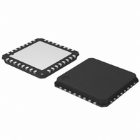
AMIS30624C6245RG ON Semiconductor, AMIS30624C6245RG Datasheet - Page 36

AMIS30624C6245RG
Manufacturer Part Number
AMIS30624C6245RG
Description
IC STEPPER DVR I2C 800MA 32-NQFP
Manufacturer
ON Semiconductor
Type
I2C Micro Stepping Motor Driverr
Datasheet
1.AMIS30624C6244RG.pdf
(56 pages)
Specifications of AMIS30624C6245RG
Applications
Stepper Motor Driver, 2 Phase
Number Of Outputs
1
Current - Output
800mA
Voltage - Supply
8 V ~ 29 V
Operating Temperature
-40°C ~ 165°C
Mounting Type
Surface Mount
Package / Case
32-VSQFP
Product
Stepper Motor Controllers / Drivers
Operating Supply Voltage
8 V to 29 V
Supply Current
800 mA
Mounting Style
SMD/SMT
Lead Free Status / RoHS Status
Lead free / RoHS Compliant
Voltage - Load
-
Lead Free Status / Rohs Status
Lead free / RoHS Compliant
Other names
766-1002-2
Available stocks
Company
Part Number
Manufacturer
Quantity
Price
Company:
Part Number:
AMIS30624C6245RG
Manufacturer:
ON Semiconductor
Quantity:
212
Company:
Part Number:
AMIS30624C6245RG
Manufacturer:
ON Semiconductor
Quantity:
1 850
Company:
Part Number:
AMIS30624C6245RG
Manufacturer:
ON Semiconductor
Quantity:
10 000
AMIS-30624
Value Table:
Table 25: Absolute Threshold Settings
MinSamples
MinSamples[2:0] is a Bemf sampling delay time expressed in number of PWM cycles, for more information please refer to the white
paper “Robust Motion Control with AMIS-3062x Stepper Motor Drivers”.
Table 27: Back emf Sample Delay Time
FS2StallEn
If AbsThr or DelThr <>0 (i.e. motion detection is enabled), then stall detection will be activated AFTER the acceleration ramp + an
additional number of full-steps, according to the following table:
Table 28: Activation Delay of Motion Detection
For more information please refer to the white paper “Robust Motion Control with AMIS-3062x Stepper Motor Drivers”.
DC100StEn
When a motor with large back – e.m.f. is operated at high velocity and low supply voltage, then the PWM duty cycle can be as high as
100 percent. This indicates that the supply is too low to generate the required torque and might also result in erroneously triggering the
stall detection. The bit “DC100StEn” (Bit 1 in Data 7 of SetStallParam) enables the function where stall detection is switched off
when PWM duty cycle equals 100 percent. For more information the white paper “Robust Motion Control with AMIS-3062x Stepper
Motor Drivers”.
Motion Qualification Mode
This mode is useful to debug motion parameters and to verify the stability of stepper motor systems. The motion qualification mode is
entered by means of the I
output can be measured. Once activated, it can only be stopped after a POR. During the back emf observation, reading of the SWI
state is internally forbidden. More information is available in the white paper “Robust Motion Control with AMIS-3062x Stepper Motor
Drivers”.
AbsThr Index
Index
C
D
A
B
E
F
0
1
2
3
4
5
6
7
8
9
Index
0
1
2
3
4
5
6
7
0
1
2
3
4
5
6
7
AbsThr Level (V)
Disable
0.5
1.0
1.5
2.0
2.5
3.0
3.5
4.0
4.5
5.0
5.5
6.0
6.5
7.0
7.5
2
C command TestBemf. The SWI pin will be converted into an analog output on which the Bemf integrator
MinSamples[2:0]
000
001
010
011
100
101
110
111
FS2StallEn[2:0]
Rev. 4 | Page 36 of 56 | www.onsemi.com
000
001
010
011
100
101
110
111
Table 26: Delta Threshold Settings
DelThr
Index
C
D
A
B
E
F
0
1
2
3
4
5
6
7
8
9
DelThr Level (V)
Disable
0.25
0.50
0.75
1.00
1.25
1.50
1.75
2.00
2.25
2.50
2.75
3.00
3.25
3.50
3.75
PWMfreq = 0
130
174
217
261
304
348
391
87
t
DELAY
Delay (Full Steps)
(μs)
0
1
2
3
4
5
6
7
PWMfreq = 1
109
130
152
174
196
43
65
87


