LMD18201T/NOPB National Semiconductor, LMD18201T/NOPB Datasheet
LMD18201T/NOPB
Specifications of LMD18201T/NOPB
*LMD18201T/NOPB
LMD18201T


Related parts for LMD18201T/NOPB


LMD18201T/NOPB Summary of contents
Page 1
... Delivers continuous output ■ Operates at supply voltages up to 55V ■ Low R typically 0.33Ω per switch at 3A DS(ON) Functional Diagram © 2011 National Semiconductor Corporation LMD18201 ■ TTL and CMOS compatible inputs ■ No “shoot-through” current ■ Thermal warning flag output at 145°C ■ ...
Page 2
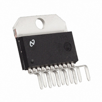
Connection Diagram and Ordering Information www.national.com Top View Order Number LMD18201T See NS Package Number TA11B 2 1079302 ...
Page 3
... Absolute Maximum Ratings If Military/Aerospace specified devices are required, please contact the National Semiconductor Sales Office/ Distributors for availability and specifications. Total Supply Voltage (V , Pin 6) S Voltage at Pins and 9 Voltage at Bootstrap Pins (Pins 1 and 11) Peak Output Current (200 ms) Continuous Output Current (Note ...
Page 4
Typical Performance Characteristics V vs Flag Current SAT R vs DS(ON) Supply Voltage Supply Current vs Frequency (V S www.national.com 1079312 1079314 = 42V) 1079316 Temperature DS(ON) 1079313 Supply Current vs Supply Voltage 1079315 Supply Current vs ...
Page 5
Test Circuit Switching Time Definitions Pinout Descriptions (See Connection Diagram) Pin 1, BOOTSTRAP 1 Input: Bootstrap capacitor pin for half H-Bridge number 1. The recommended capacitor (10 nF) is connected between pins 1 and 2. Pin 2, OUTPUT 1: Half ...
Page 6
Sign/magnitude PWM consists of separate direction (sign) and amplitude (magnitude) signals (see solute) magnitude signal is duty-cycle modulated, and the absence of a pulse signal (a continuous logic low level) rep- www.national.com FIGURE 2. Locked Anti-Phase PWM Control resents zero ...
Page 7
FIGURE 4. Transitions in Brake, Direction, or PWM Must be Separated by At Least 1 μsec SIGNAL TRANSITION REQUIREMENTS To ensure proper internal logic performance good prac- tice to avoid aligning the falling and rising edges of input ...
Page 8
V thereby providing a gate drive voltage greater than V S This switching action is controlled by a continuously running ...
Page 9
CURRENT SENSING In many motor control applications it is desirable to sense and control the current through the motor. For these types of ap- plications a companion product, the LMD18200, is also avail- able. The LMD18200 is identical to the ...
Page 10
Physical Dimensions www.national.com inches (millimeters) unless otherwise noted 11-Lead TO-220 Power Package (T) Order Number LMD18201T NS Package Number TA11B 10 ...
Page 11
Notes 11 www.national.com ...
Page 12
... For more National Semiconductor product information and proven design tools, visit the following Web sites at: www.national.com Products Amplifiers www.national.com/amplifiers Audio www.national.com/audio Clock and Timing www.national.com/timing Data Converters www.national.com/adc Interface www.national.com/interface LVDS www.national.com/lvds Power Management www.national.com/power Switching Regulators www.national.com/switchers LDOs www.national.com/ldo LED Lighting www ...