LMD18201T/NOPB National Semiconductor, LMD18201T/NOPB Datasheet - Page 8
LMD18201T/NOPB
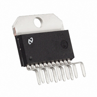
Manufacturer Part Number
LMD18201T/NOPB
Description
IC H BRIDGE 3A 55V TO220-11
Manufacturer
National Semiconductor
Specifications of LMD18201T/NOPB
Applications
DC Motor Driver, Stepper Motor Driver, H Bridge
Number Of Outputs
1
Current - Output
3A
Voltage - Supply
12 V ~ 55 V
Operating Temperature
-40°C ~ 125°C
Mounting Type
Through Hole
Package / Case
TO-220-11 (Bent and Staggered Leads)
Lead Free Status / RoHS Status
Lead free / RoHS Compliant
Voltage - Load
-
Lead Free Status / Rohs Status
RoHS Compliant part
Electrostatic Device
Other names
*LMD18201T
*LMD18201T/NOPB
LMD18201T
*LMD18201T/NOPB
LMD18201T


www.national.com
shown in
switched to ground and charged to about 14V, then switched
to V
This switching action is controlled by a continuously running
internal 300 kHz oscillator. The rise time of this drive voltage
is typically 20 μs which is suitable for operating frequencies
up to 1 kHz.
For higher switching frequencies, the LMD18201 provides for
the use of external bootstrap capacitors. The bootstrap prin-
ciple is in essence a second charge pump whereby a large
value capacitor is used which has enough energy to quickly
charge the parasitic gate input capacitance of the power de-
vice resulting in much faster rise times. The switching action
is accomplished by the power switches themselves
6). External 10 nF capacitors, connected from the outputs to
the bootstrap pins of each high-side switch provide typically
less than 100 ns rise times allowing switching frequencies up
to 500 kHz.
S
thereby providing a gate drive voltage greater than V
FIGURE 5. Internal Charge Pump Circuitry
(Figure
FIGURE 6. Bootstrap Circuitry
5), an internal capacitor is alternately
1079306
1079307
(Figure
S
.
8
INTERNAL PROTECTION DIODES
A major consideration when switching current through induc-
tive loads is protection of the switching power devices from
the large voltage transients that occur. Each of the four
switches in the LMD18201 have a built-in protection diode to
clamp transient voltages exceeding the positive supply or
ground to a safe diode voltage drop across the switch.
The reverse recovery characteristics of these diodes, once
the transient has subsided, is important. These diodes must
come out of conduction quickly and the power switches must
be able to conduct the additional reverse recovery current of
the diodes. The reverse recovery time of the diodes protecting
the sourcing power devices is typically only 70 ns with a re-
verse recovery current of 1A when tested with a full 3A of
forward current through the diode. For the sinking devices the
recovery time is typically 100 ns with 4A of reverse current
under the same conditions.
Typical Applications
BASIC MOTOR DRIVER
The LMD18201 can directly interface to any Sign/Magnitude
PWM controller. The LM629 is a motion control processor that
outputs a Sign/Magnitude PWM signal to coordinate either
positional or velocity control of DC motors. The LMD18201
provides fully protected motor driver stage.
Related parts for LMD18201T/NOPB
Image
Part Number
Description
Manufacturer
Datasheet
Request
R

Part Number:
Description:
IC, MOTOR CTRL, HALF BRIDGE 3A TO-220-11
Manufacturer:
National Semiconductor
Datasheet:

Part Number:
Description:
National Semiconductor [8-Bit D/A Converter]
Manufacturer:
National Semiconductor
Datasheet:
Part Number:
Description:
National Semiconductor [Media Coprocessor]
Manufacturer:
National Semiconductor
Datasheet:
Part Number:
Description:
Digitally Controlled Tone and Volume Circuit with Stereo Audio Power Amplifier, Microphone Preamp Stage and National 3D Sound
Manufacturer:
National Semiconductor
Datasheet:
Part Number:
Description:
Digitally Controlled Tone and Volume Circuit with Stereo Audio Power Amplifier, Microphone Preamp Stage and National 3D Sound
Manufacturer:
National Semiconductor
Datasheet:
Part Number:
Description:
AC97 Rev 2 Codec with Sample Rate Conversion and National 3D Sound
Manufacturer:
National Semiconductor
Part Number:
Description:
Manufacturer:
National Semiconductor
Datasheet:
Part Number:
Description:
Manufacturer:
National Semiconductor
Datasheet:
Part Number:
Description:
General Purpose, Low Voltage, Low Power, Rail-to-Rail Output Operational Amplifiers
Manufacturer:
National Semiconductor
Datasheet:
Part Number:
Description:
8-bit 20 MSPS flash A/D converter.
Manufacturer:
National Semiconductor
Datasheet:
Part Number:
Description:
Low Noise Quad Operational Amplifier
Manufacturer:
National Semiconductor
Datasheet:
Part Number:
Description:
Quad Differential Line Receivers
Manufacturer:
National Semiconductor
Datasheet:
Part Number:
Description:
Quad High Speed Trapezoidal? Bus Transceiver
Manufacturer:
National Semiconductor
Datasheet:
Part Number:
Description:
Dual Line Receiver
Manufacturer:
National Semiconductor
Datasheet: