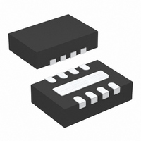
LTC4354IDDB#TRPBF Linear Technology, LTC4354IDDB#TRPBF Datasheet - Page 3

LTC4354IDDB#TRPBF
Manufacturer Part Number
LTC4354IDDB#TRPBF
Description
IC MON DIODE-OR CTRLR NEG 8DFN
Manufacturer
Linear Technology
Datasheet
1.LTC4354CS8PBF.pdf
(12 pages)
Specifications of LTC4354IDDB#TRPBF
Applications
-48V Dist Power Systems, AdvancedTCA ® Systems
Fet Type
N-Channel
Number Of Outputs
2
Internal Switch(s)
No
Delay Time - Off
700ns
Voltage - Supply
4.5 V ~ 11.75 V
Current - Supply
1.2mA
Operating Temperature
-40°C ~ 85°C
Mounting Type
Surface Mount
Package / Case
8-DFN
Lead Free Status / RoHS Status
Lead free / RoHS Compliant
Delay Time - On
-
Available stocks
Company
Part Number
Manufacturer
Quantity
Price
temperature range, otherwise specifications are at T
SYMBOL
V
∆V
V
I
V
I
∆V
∆V
t
V
I
I
Note 1: Stresses beyond those listed under Absolute Maximum Ratings
may cause permanent damage to the device. Exposure to any Absolute
Maximum Rating condition for extended periods may affect device
reliability and lifetime.
Note 2: I
by 100mV from the value with 2mA of current.
ELECTRICAL CHARACTERISTICS
CC
GATE
OFF
FAULT
D
Z
CC
GATE
FAULT
Z
SD
SD(FLT)
CC
is defined as the current level where the V
PARAMETER
Internal Shunt Regulator Voltage
Internal Shunt Regulator Load Regulation
Operating Voltage Range
V
GATE Pins Output High Voltage
GATE Pins Pull-Up Current
GATE Pins Pull-Down Current
Source Drain Sense Threshold Voltage
Source Drain Fault Detection Threshold
Gate Turn-Off Time in Fault Condition
FAULT Pin Output Low
FAULT Pin Leakage Current
Drain Pin Input Current
CC
Supply Current
CC
voltage is lower
A
CONDITIONS
I
I
V
V
V
V
V
V
(V
(V
C
I
V
V
V
= 25°C. I
CC
CC
FAULT
CC
CC
CC
CC
SD
SD
GATE
FAULT
DX
DX
SS
SS
= 5mA
= 2mA to 10mA
= (V
= 5V
= 10.25V
= 5V
= 60mV; V
= 0V; V
= 0V
= 80V
– V
– V
The
= 3300pF; V
= 5mA
= 5V
Z
DX
DX
CC
– 0.1V), Note 2
●
)
); V
GATE
denotes the specifications which apply over the full operating
= 5mA, V
CC
GATE
= 5.5V
= 7V to V
Note 3: An internal shunt regulator limits the V
above V
part.
Note 4: All currents into pins are positive; all voltages are referenced to
V
GATE
SS
= 5.5V
unless otherwise specified.
≤ 2V; V
SS
SS
Z
= 0V unless otherwise noted.
. Driving this pin to voltages beyond the clamp may damage the
SD
= –0.4V
●
●
●
●
●
●
●
●
10.25
MIN
4.75
–3.5
–15
200
4.5
0.5
1.1
10
15
10
CC
–2.5
TYP
200
–30
260
200
1.2
0.8
0.7
1.5
11
30
30
pin to less than 12V
LTC4354
11.75
10.25
MAX
–1.5
300
–60
320
400
1.1
1.2
1.9
60
55
±1
V
2
Z
UNITS
4354fb
3
mV
mA
mA
mV
mV
mV
mA
µA
µA
µA
µA
µs
V
V
V
V


