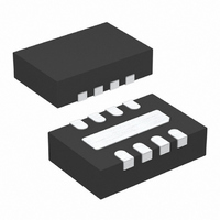
LTC4354IDDB#TRPBF Linear Technology, LTC4354IDDB#TRPBF Datasheet - Page 6

LTC4354IDDB#TRPBF
Manufacturer Part Number
LTC4354IDDB#TRPBF
Description
IC MON DIODE-OR CTRLR NEG 8DFN
Manufacturer
Linear Technology
Datasheet
1.LTC4354CS8PBF.pdf
(12 pages)
Specifications of LTC4354IDDB#TRPBF
Applications
-48V Dist Power Systems, AdvancedTCA ® Systems
Fet Type
N-Channel
Number Of Outputs
2
Internal Switch(s)
No
Delay Time - Off
700ns
Voltage - Supply
4.5 V ~ 11.75 V
Current - Supply
1.2mA
Operating Temperature
-40°C ~ 85°C
Mounting Type
Surface Mount
Package / Case
8-DFN
Lead Free Status / RoHS Status
Lead free / RoHS Compliant
Delay Time - On
-
Available stocks
Company
Part Number
Manufacturer
Quantity
Price
OPERATIO
LTC4354
TI I G DIAGRA
High availability systems often employ parallel-connected
power supplies or battery feeds to achieve redundancy
and enhance system reliability. ORing diodes have been a
popular means of connecting these supplies at the point of
load. The disadvantage of this approach is the significant
forward voltage drop and resulting efficiency loss. This
drop reduces the available supply voltage and dissipates
significant power. A desirable circuit would behave like
diodes but without the voltage drop and the resulting
power dissipation.
The LTC4354 is a negative voltage diode-OR controller
that drives two external N-channel MOSFETs as pass
transistors to replace ORing diodes. The MOSFETs are
connected together at the source pins. The common
source node is connected to the V
negative supply of the device. It is also connected to the
positive inputs of the amplifiers that control the gates to
regulate the voltage drop across the pass transistors.
Using N-channel MOSFETs to replace Schottky diodes
reduces the power dissipation and eliminates the need for
costly heat sinks or large thermal layouts in high power
applications.
At power-up, the initial load current flows through the
body diode of the MOSFET and returns to the supply with
the lower terminal voltage. The associated gate pin will
immediately start ramping up and turn on the MOSFET.
The amplifier tries to regulate the voltage drop between the
source and drain connections to 30mV. If the load current
causes more than 30mV of drop, the gate rises to further
6
W U
U
V
W
SS
V
– V
GATE
DX
–400mV
100mV
SS
pin which is the
t
OFF
enhance the MOSFET. Eventually the MOSFET gate is
driven fully on and the voltage drop is equal to the R
• I
When the power supply voltages are nearly equal, this
regulation technique ensures that the load current is
smoothly shared between them without oscillation. The
current level flowing through each pass transistor de-
pends on the R
impedance of the supplies.
In the case of supply failure, such as if the supply that is
conducting most or all of the current is shorted to the
return side, a large reverse current starts flowing through
the MOSFET that is on, from any load capacitance and
through the body diode of the other MOSFET, to the
second supply. The LTC4354 detects this failure condition
as soon as it appears and turns off the MOSFET in less than
1µs. This fast turn-off prevents the reverse current from
ramping up to a damaging level.
In the case where the pass transistor is fully on but the
voltage drop across it exceeds the fault threshold, the
FAULT pin goes high impedance. This allows an LED or
optocoupler to turn on indicating that one or both of the
pass transistors have failed.
The LTC4354 is powered from system ground through a
current limiting resistor. An internal shunt regulator that
can sink up to 20mA clamps the V
A 1µF bypass capacitor across V
supply transients and supplies AC current to the device.
2V
LOAD
.
DS(ON)
of the MOSFET and the output
CC
CC
4354 TD01
pin to 11V above V
and V
SS
pins filters
DS(ON)
4354fb
SS
.


