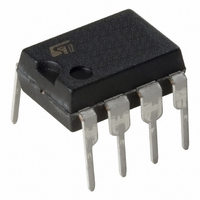
L6561 STMicroelectronics, L6561 Datasheet - Page 3

L6561
Manufacturer Part Number
L6561
Description
IC PFC CTRLR TRANSITION 8DIP
Manufacturer
STMicroelectronics
Datasheet
1.L6561D013TR.pdf
(13 pages)
Specifications of L6561
Mode
Discontinuous (Transition)
Current - Startup
50µA
Voltage - Supply
11 V ~ 18 V
Operating Temperature
-25°C ~ 125°C
Mounting Type
Through Hole
Package / Case
8-DIP
Maximum Operating Temperature
+ 150 C
Mounting Style
Through Hole
Minimum Operating Temperature
- 40 C
Totem Pole Output Current
±400mA
For Use With
497-3823 - EVAL BOARD FOR HF TL BALLAST
Lead Free Status / RoHS Status
Lead free / RoHS Compliant
Frequency - Switching
-
Lead Free Status / Rohs Status
Lead free / RoHS Compliant
Other names
497-3653
Available stocks
Company
Part Number
Manufacturer
Quantity
Price
Part Number:
L6561
Manufacturer:
ST
Quantity:
20 000
Company:
Part Number:
L6561/NOPB
Manufacturer:
ST
Quantity:
2 230
Company:
Part Number:
L65610
Manufacturer:
RAYTHEON
Quantity:
230
Company:
Part Number:
L6561013TR
Manufacturer:
PANASONIC
Quantity:
60 000
Table 5. Electrical Characteristics
(V
SUPPLY VOLTAGE SECTION
SUPPLY CURRENT SECTION
ERROR AMPLIFIER SECTION
MULTIPLIER SECTION
CURRENT SENSE COMPARATOR
ZERO CURRENT DETECTOR
Symbol
I
V
V
-----------------
START-U
V
V
t
CC
I
CC OFF
V
V
V
COMP
d (H-L)
V
V
CC ON
V
Hys
V
I
COMP
GB
I
G
MULT
V
I
V
INV
CC
Iq
ZCD
ZCD
ZCD
I
CS
INV
K
mult
CC
CS
q
CS
Z
V
= 14.5V; T
Pin
8
8
8
8
8
8
8
8
8
8
1
1
2
2
3
4
4
4
4
5
5
5
amb
Operating Range
Turn-on Threshold
Turn-off Threshold
Hysteresis
Start-up Current
Quiescent Current
Operating Supply Current
Quiescent Current
Zener Voltage
Voltage Feedback Input
Threshold
Line Regulation
Input Bias Current
Voltage Gain
Gain Bandwidth
Source Current
Sink Current
Upper Clamp Voltage
Lower Clamp Voltage
Linear Operating Voltage
Output Max. Slope
Gain
Current Sense Reference
Clamp
Input Bias Current
Delay to Output
Current Sense Offset
Input Threshold Voltage Rising
Edge
Hysteresis
Upper Clamp Voltage
Upper Clamp Voltage
= -25°C to 125°C;unless otherwise specified)
Parameter
after turn-on
before turn-on (V
C
in OVP condition V
V
V
I
T
12V < V
V
Open loop
V
V
I
I
V
V
V
V
V
(1)
(1)
I
I
CC
SOURCE
Sink
ZCD
ZCD
amb
PIN5
PIN5
CC
COMP
COMP
MULT
COMP
MULT
COMP
OS
L
= 1nF @ 70KHz
V
= 25mA
= 0.5mA
= 0
= 12 to 18V
MULT
= 20 A
= 3mA
= 25°C
= from 0V to 0.5V
= 2.5V
150mV, V
= 4V, V
= 4V, V
= Upper Clamp Voltage
= Upper Clamp Voltage
Test Condition
150mV, V
CC
= 0.5mA
= 1V V
< 18V
INV
INV
CC
COMP
CC
CC
= 2.4V
= 2.6V
pin1
> V
=11V)
< V
= 2.7V
= 4V
CC off
CC off
2.465
0 to 3
Min.
2.44
1.65
0.45
8.7
2.2
2.5
1.6
0.3
4.5
4.7
11
11
20
20
18
60
-2
0 to 3.5
-0.05
Typ.
2.25
-0.1
200
9.5
2.5
2.6
1.4
1.4
2.5
4.5
5.8
1.9
0.6
1.7
2.1
0.5
5.1
5.2
12
50
50
20
80
-4
4
2
1
0
2.535
Max.
10.3
2.56
0.75
450
2.8
5.5
2.1
2.1
1.8
0.7
5.9
6.1
18
13
90
90
22
15
-1
-8
-1
4
5
L6561
MHz
Unit
mA
mA
mA
mA
mV
mA
mA
1/V
mV
dB
ns
V
V
V
V
V
V
V
V
V
V
V
V
V
V
V
A
A
A
A
3/13


