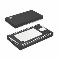
LTC3577EUFF#PBF Linear Technology, LTC3577EUFF#PBF Datasheet - Page 47

LTC3577EUFF#PBF
Manufacturer Part Number
LTC3577EUFF#PBF
Description
IC PWR MANAGEMENT HANDHELD 44QFN
Manufacturer
Linear Technology
Datasheet
1.LTC3577EUFFPBF.pdf
(54 pages)
Specifications of LTC3577EUFF#PBF
Applications
Handheld/Mobile Devices
Voltage - Supply
4.35 V ~ 5.5 V
Operating Temperature
-40°C ~ 85°C
Mounting Type
Surface Mount
Package / Case
44-QFN
Lead Free Status / RoHS Status
Lead free / RoHS Compliant
Current - Supply
-
Available stocks
Company
Part Number
Manufacturer
Quantity
Price
OPERATION
Hard Reset Timing
Hard reset provides an ultralow power-down state for
shipping or long-term storage as well as a way to power
down the application in case of a software lock-up. In the
case of software lock-up ON is brought low by the user
applying the pushbutton. If the user holds the pushbutton
for 5 seconds a hard reset event (HRST) will occur placing
the pushbutton circuitry in the PDN1 state. At this point
the bucks, LDOs and LED backlight will all be shut down
and WAKE and PG_DCDC will both go low. Following a 1
second power-down period the pushbutton circuitry will
enter the hard reset state (HR).
Holding ON low through the 1 second power-down period
will not cause a power-up event at end of the 1second period.
The ON must be brought high following the power-down
event and then go low for again for 400ms to establish a
valid power-up event as shown in Figure 24.
PG_DCDC
PWR_ON
ON (PB)
PBSTAT
STATE
BUCKS
WAKE
BAT
Figure 24. Hard Reset Timing
PON
5SEC
PDN1
1SEC
HR
400ms
1 2 3
PUP
3577 F24
Power-Up Sequencing
Figure 25 shows the actual power-up sequencing of the
LTC3577. Buck1, buck2 and buck3 are all initially disabled
(0V). Once the pushbutton has been applied (ON low) for
400ms, WAKE goes high and buck1 is enabled. Buck1
slews up and enters regulation once enabled. The actual
slew rate is controlled by the soft-start function of buck1
in conjunction with output capacitance and load (see the
“Step-Down Switching Regulator Operation” section for
more information). When buck1 is within about 8% of fi nal
regulation, buck2 is enabled and slews up into regulation.
Finally when buck2 is within about 8% of fi nal regulation,
buck3 is enabled and slews up into regulation. 230ms
after buck3 is within 8% of fi nal regulation the PG_DCDC
output will go high impedance (not shown in Figure 25).
The regulators in Figure 25 are slewing up with nominal
output capacitors and no load. Adding a load or increasing
output capacitance on any of the outputs will reduce the
slew rate and lengthen the time it takes the regulator to get
into regulation. Reducing the slew rate also pushes out the
time until the next regulator is enabled proportionally.
BUCK1
2V/DIV
BUCK2
1V/DIV
BUCK3
1V/DIV
WAKE
0V
0V
0V
1
0
Figure 25. Power-Up Sequencing
LTC3577/LTC3577-1
50μs/DIV
3577 F23
47
3577fa


