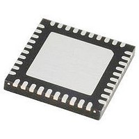
IR3523MTRPBF International Rectifier, IR3523MTRPBF Datasheet - Page 27

IR3523MTRPBF
Manufacturer Part Number
IR3523MTRPBF
Description
IC XPHASE3 CTLR VR11.1 40-MLPQ
Manufacturer
International Rectifier
Series
XPhase3™r
Datasheet
1.IR3523MTRPBF.pdf
(37 pages)
Specifications of IR3523MTRPBF
Applications
Processor
Current - Supply
10mA
Voltage - Supply
4.75 V ~ 7.5 V
Operating Temperature
0°C ~ 100°C
Mounting Type
Surface Mount
Package / Case
40-MLPQ
Ic Function
Dual Output Control IC
Supply Voltage Range
4.75V To 7.5V
Operating Temperature Range
0°C To +150°C
Digital Ic Case Style
MLPQ
No. Of Pins
40
Controller Type
XPhase
Rohs Compliant
Yes
Package
40-Lead MLPQ
Circuit
X-Phase Control IC
Switch Freq (khz)
250kHz to 1.5MHz
Pbf
PbF Option Available
Lead Free Status / RoHS Status
Lead free / RoHS Compliant
No Load Offset Setting Resistor RFB11, RFB13, RTHERM1 and Adaptive Voltage Positioning Resistor
RDRP11 for Output1
Define R
offset voltage V
equation in the ELECTRICAL CHARACTERISTICS Table, then the effective offset resistor value R
determined from (12).
Adaptive voltage positioning lowers the converter voltage by R
the converter. Pre-select feedback resistor R
Calculate the desired effective feedback resistor at the maximum temperature R
A negative temperature constant (NTC) thermistor R
stage for the inductor DCR thermal compensation. Pre-select the value of R
R
as the NTC thermistor resistance at maximum allowed temperature, T
Select the series resistor R
which has non-linear characteristics in the operational temperature range.
Use equation (17) to determine R
R
FB_R
FB
13
=
at room temperature but also bigger than R
Page 27 of 37
(
FB_R
R
THERM
is the effective offset resistor at room temperature equals to R
1
+
O_NLOFST
R
TMAX
1
)
2
R
−
TMAX
4
above the DAC voltage, calculate the sink current from the FB1 pin I
R
R
( *
R
FB13
FB
R
1
DRP
FB
R
FB
1
11
THERM
_
=
11
_
R
=
by using equation (16). R
FB11.
M
R
=
=
THERM
R
1
=
V
*
FB
R
1
O
FB
R
R
G
_
_
TMAX
DRP
I
CS
R
_
NLOFST
1
FB
R
−
*
∗
11
1
1
∗
EXP
R
−
R
∗
R
FB,
n
L
FB
(
L
R
R
∗
_
13
_
O
THERM
MAX
[
R
and calculate the droop resistor RDRP,
ROOM
B
*
O
+
THERM
n
1
R
FB_M
1
THERM
−
*
THERM1
R
G
1
TMAX
CS
( *
at the maximum allowed temperature. R
2
1
T
1
L
* )
FB13
_
1
MAX
R
is required to sense the temperature of the power
O
FB
*I
_
O,
is incorporated to linearize the NTC thermistor
R
−
*
where R
T
R
_
MAX.
FB
ROOM
1
_
M
/(
R
)]
R
O
THERM.
FB
TMAX1
is the required output impedance of
FB11
(17)
_
FB_M
R
(14)
−
(12)
(13)
//(R
R
is calculated from (15).
FB
R
using (14)
_
THERM
FB13
M
))
(15)
−
+R
June 20, 2008
(
R
must be bigger than
THERM1
THERM
TMAX1
1
+
FB1
IR3523
T
). Given the
TMAX
FB1
is defined
using the
1
)
can be
(16)


