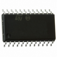
L6610D STMicroelectronics, L6610D Datasheet - Page 22

L6610D
Manufacturer Part Number
L6610D
Description
IC CTRLR HOUSEKEEPING BCD 24SOIC
Manufacturer
STMicroelectronics
Datasheet
1.L6610DTR.pdf
(29 pages)
Specifications of L6610D
Applications
Programmable Housekeeping Controller
Voltage - Supply
4.2 V ~ 7 V
Current - Supply
5mA
Operating Temperature
0°C ~ 105°C
Mounting Type
Surface Mount
Package / Case
24-SOIC (7.5mm Width)
Lead Free Status / RoHS Status
Lead free / RoHS Compliant
Voltage - Input
-
Available stocks
Company
Part Number
Manufacturer
Quantity
Price
Part Number:
L6610D
Manufacturer:
ST
Quantity:
20 000
L6610
– Dmon input undervoltage: when an undervoltage on Dmon is detected, MFAULT is put high, Cout is
– Overcurrent protection: the IC provides an on-board overcurrent protection for 5V and 12V main input
Figure 22. Fault timing diagram
The overcurrent function is implemented with a comparator detecting the voltage drop across an external cur-
rent sense resistor in series with the output. If this voltage gets higher than a fixed threshold (50mV for 5V input
monitoring and 120mV for 12V input monitoring), an internal MAIN_OC signal is generated; a 450 s debounce
time exists to assert MFAULT high. Depending on the selected operating mode, MFAULT will be latched high
(default latching mode) or pulled low again after about 1s to allow autorecovery (bounce mode).
To disable this function, the input sense pin may be left open (an internal pull-down is provided), shorted to
ground or shorted to 5V or 12V pin.
22/29
DFAULT; in the "Application ideas" section, another simple circuit is showed to guarantee the same pro-
tection without the SCR.
pulled low (an internal OCP_BOUNCE signal is generated, see fig. 21) and PW_OK falls down. This
function is enabled 64ms after the UVLO signal falls down. Debounce logic is implemented so that
MFAULT and OCP_BOUNCE signals are generated only if the undervoltage condition lasts more than
500µs.
The Dmon UV and OV protections can be set to work with thresholds set for 5V or 3.3V output voltage:
the choice depends on the IC programming.
pins. Optionally, it is possible to switch the monitoring from 5V to 3.3V output using the IC programming
(see "On board trimming and mode operating" section).
(*) Dmon is connected to the Auxiliary output Rail
Auxiliary output’s overvoltage
Dmon
Dfault current
Mfault
POK
(*)
Output
Mfault
POK
Main output’s overvoltage
Dmon
Cout
Mfault
POK
(*)
Auxiliary output’s undervoltage
Output
Mfault
POK
Main output’s undervoltage


