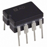
AD737AQ Analog Devices Inc, AD737AQ Datasheet - Page 12

AD737AQ
Manufacturer Part Number
AD737AQ
Description
IC AC RMS TO DC CONV 5V 8-CDIP
Manufacturer
Analog Devices Inc
Datasheet
1.AD737JNZ.pdf
(24 pages)
Specifications of AD737AQ
Rohs Status
RoHS non-compliant
Current - Supply
170mA
Voltage - Supply
±5.0V
Mounting Type
Through Hole
Package / Case
8-CDIP (0.300", 7.62mm)
For Use With
AD737-EVALZ - BOARD EVALUATION FOR AD737
Available stocks
Company
Part Number
Manufacturer
Quantity
Price
Part Number:
AD737AQ
Manufacturer:
ADI/亚德诺
Quantity:
20 000
AD737
THEORY OF OPERATION
As shown in Figure 24, the AD737 has four functional subsec-
tions: an input amplifier, a full-wave rectifier, an rms core, and a
bias section. The FET input amplifier allows a high impedance,
buffered input at Pin 2 or a low impedance, wide dynamic range
input at Pin 1. The high impedance input, with its low input bias
current, is ideal for use with high impedance input attenuators.
The input signal can be either dc-coupled or ac-coupled to the
input amplifier. Unlike other rms converters, the AD737 permits
both direct and indirect ac coupling of the inputs. AC coupling is
provided by placing a series capacitor between the input signal
and Pin 2 (or Pin 1) for direct coupling and between Pin 1 and
ground (while driving Pin 2) for indirect coupling.
POWER
The output of the input amplifier drives a full-wave precision
rectifier which, in turn, drives the rms core. It is the core that
provides the essential rms operations of squaring, averaging,
and square rooting, using an external averaging capacitor, C
Without C
unprocessed, as is done with the average responding connection
(see Figure 26). In the average responding mode, averaging is
carried out by an RC post filter consisting of an 8 kΩ internal
scale factor resistor connected between Pin 6 and Pin 8 and an
V
DOWN
–V
IN
C
V
S
C
IN
OPTIONAL RETURN PATH
1
2
3
4
CURRENT
MODE
ABSOLUTE
VALUE
1
NEGATIVE SUPPLY
OP AMP
TRANSLINEAR
AV
POSITIVE SUPP LY
B
8kΩ
FET
<10pA
SECTION
Figure 24. AD737 True RMS Circuit (Test Circuit)
, the rectified input signal passes through the core
BIAS
CORE
RMS
COMMON
C
DC
C =
33µF
AC
C
10µF
A
+
+
0.1µF
0.1µF
8kΩ
+V
–V
S
S
COM
OUTPUT
8
7
6
5
+V
C
S
+
AV
C
10µF
(OPTIONAL
LPF)
F
AV
Rev. H | Page 12 of 24
.
external averaging capacitor, C
tional filtering stage reduces any output ripple that was not
removed by the averaging capacitor.
Finally, the bias subsection permits a power-down function.
This reduces the idle current of the AD737 from 160 μA to
30 μA. This feature is selected by connecting Pin 3 to Pin 7
(+V
TYPES OF AC MEASUREMENT
The AD737 is capable of measuring ac signals by operating as
either an average responding converter or a true rms-to-dc con-
verter. As its name implies, an average responding converter
computes the average absolute value of an ac (or ac and dc)
voltage or current by full-wave rectifying and low-pass filtering
the input signal; this approximates the average. The resulting
output, a dc average level, is then scaled by adding (or reducing)
gain; this scale factor converts the dc average reading to an rms
equivalent value for the waveform being measured. For example,
the average absolute value of a sine wave voltage is 0.636 that of
V
Therefore, for sine wave voltages, the required scale factor is
1.11 (0.707 divided by 0.636).
In contrast to measuring the average value, true rms measure-
ment is a universal language among waveforms, allowing the
magnitudes of all types of voltage (or current) waveforms to be
compared to one another and to dc. RMS is a direct measure of
the power or heating value of an ac voltage compared to that of
a dc voltage; an ac signal of 1 V rms produces the same amount
of heat in a resistor as a 1 V dc signal.
Mathematically, the rms value of a voltage is defined (using a
simplified equation) as
This involves squaring the signal, taking the average, and then
obtaining the square root. True rms converters are smart recti-
fiers; they provide an accurate rms reading regardless of the
type of waveform being measured. However, average responding
converters can exhibit very high errors when their input signals
deviate from their precalibrated waveform; the magnitude of
the error depends on the type of waveform being measured. As
an example, if an average responding converter is calibrated to
measure the rms value of sine wave voltages and then is used to
measure either symmetrical square waves or dc voltages, the
converter has a computational error 11% (of reading) higher
than the true rms value (see Table 5).
The transfer function for the AD737 is
PEAK
S
).
V rms =
V
; the corresponding rms value is 0.707 times V
OUT
=
Avg
Avg
(
(
V
V
2
IN
)
2
)
F
. In the rms circuit, this addi-
PEAK
.


