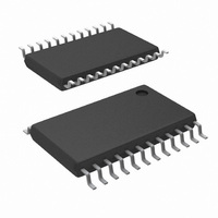
LM96080CIMT/NOPB National Semiconductor, LM96080CIMT/NOPB Datasheet - Page 14

LM96080CIMT/NOPB
Manufacturer Part Number
LM96080CIMT/NOPB
Description
IC HARDWARE MONITOR 24-TSSOP
Manufacturer
National Semiconductor
Series
PowerWise®r
Datasheet
1.LM96080CIMTNOPB.pdf
(30 pages)
Specifications of LM96080CIMT/NOPB
Function
Hardware Monitor
Topology
ADC (Sigma Delta), Comparator, Fan Speed Counter, Register Bank
Sensor Type
External & Internal
Sensing Temperature
-40°C ~ 125°C, External Sensor
Output Type
I²C™
Output Alarm
No
Output Fan
Yes
Voltage - Supply
3 V ~ 5.5 V
Operating Temperature
-40°C ~ 125°C
Mounting Type
Surface Mount
Package / Case
24-TSSOP
Lead Free Status / RoHS Status
Lead free / RoHS Compliant
Other names
LM96080CIM
Available stocks
Company
Part Number
Manufacturer
Quantity
Price
Company:
Part Number:
LM96080CIMT/NOPB
Manufacturer:
National Semiconductor
Quantity:
135
Company:
Part Number:
LM96080CIMT/NOPB
Manufacturer:
NS
Quantity:
175
www.national.com
4.0 ANALOG INPUTS
The 10-bit ADC has a 2.5 mV (2.56/2
to 2.5575V (2.56 - 1 LSb) input range. This is true for all ana-
log inputs. In most monitoring applications, these inputs
would most often be connected to power supplies. The 2.5,
3.3, ±5 and ±12 volt inputs should be attenuated with external
resistors to any desired value within the input range. Care
should be taken not to exceed V
A typical application, such as is shown in
lect the input voltage divider to provide 1.9V at the analog
inputs of the LM96080. This is sufficiently high for good res-
olution of the voltage, yet leaves headroom for upward ex-
cursions from the supply of about 25%. To simplify the
process of resistor selection, set the value of R2 first. Select
a value for R2 or R4 between 10 kΩ and 100 kΩ. This is low
enough to avoid errors due to input leakage currents yet high
enough to protect both the inputs under overdrive conditions
as well as minimize loading of the source. Then select R1 or
R3 to provide a 1.9V input as show in
table provide approximately 1.9V at the analog inputs.
FIGURE 3. Input Examples. Resistor values shown in
Measure-
Voltage
ments
+2.5V
+3.3V
+5.0V
+12V
−12V
(V
−5V
TABLE 2: V
S
)
R1 or R3 R2 or R4
23.7 kΩ
22.1 kΩ
160 kΩ
160 kΩ
24 kΩ
36 kΩ
IN
= 1.9V for Different R Values
14.7 kΩ
30.1 kΩ
35.7 kΩ
16.2 kΩ
75 kΩ
30 kΩ
+
at any time.
10
Figure
) LSb , yielding a 0V
( ADC code 760)
Figure
Analog Inputs
3.
Voltage
+1.9V
+1.9V
+1.9V
+1.9V
+1.9V
+1.9V
3, might se-
at
30070111
14
For positive input voltages, the equation for calculating R1 is
as follows:
For negative input voltages, the equation for calculating R3 is
as follows:
External resistors should be included to limit input currents to
the values given in the ABSOLUTE MAXIMUM RATINGS for
Input Current At Any Pin. Inputs with the attenuator networks
will usually meet these requirements. If it is possible for inputs
without attenuators to be turned on while LM96080 is pow-
ered off, additional resistors of about 10 kΩ should be added
in series with the inputs to limit the input current.
5.0 SUPPLY CURRENT (I
The measured supply current (I
istics are only for the round robin conversion and the shut-
down mode at a certain supply voltage. To calculate the
supply current I
voltages, use the equation below.
The I
from the plots shown in the Typicals Performance Character-
istics section.
+
TEMP
, I
+
VOLTAGE
R3 = [ (V
+
FIGURE 4. I
R1 = [ (V
in the round robin mode at different supply
, and I
S
− V
S
+
+
)
SHUTDOWN
− V
IN
+
) / (V
Calculation
IN
+
) in the Electrical Character-
) / V
IN
− 5V)] R4
IN
values can be obtained
] R2
30070139


