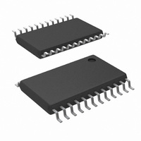
LM96080CIMT/NOPB National Semiconductor, LM96080CIMT/NOPB Datasheet - Page 25

LM96080CIMT/NOPB
Manufacturer Part Number
LM96080CIMT/NOPB
Description
IC HARDWARE MONITOR 24-TSSOP
Manufacturer
National Semiconductor
Series
PowerWise®r
Datasheet
1.LM96080CIMTNOPB.pdf
(30 pages)
Specifications of LM96080CIMT/NOPB
Function
Hardware Monitor
Topology
ADC (Sigma Delta), Comparator, Fan Speed Counter, Register Bank
Sensor Type
External & Internal
Sensing Temperature
-40°C ~ 125°C, External Sensor
Output Type
I²C™
Output Alarm
No
Output Fan
Yes
Voltage - Supply
3 V ~ 5.5 V
Operating Temperature
-40°C ~ 125°C
Mounting Type
Surface Mount
Package / Case
24-TSSOP
Lead Free Status / RoHS Status
Lead free / RoHS Compliant
Other names
LM96080CIM
Available stocks
Company
Part Number
Manufacturer
Quantity
Price
Company:
Part Number:
LM96080CIMT/NOPB
Manufacturer:
National Semiconductor
Quantity:
135
Company:
Part Number:
LM96080CIMT/NOPB
Manufacturer:
NS
Quantity:
175
2-3 FAN1 RPM
4-5 FAN2 RPM
4-7 Temp [3:0]
Bit
Bit
0
1
6
7
0
1
2
3
12.8 Fan Divisor/RST_OUT/OS Register —Address 05h
Power on – <7:0> is 0001 0100
12.9 OS Configuration/Temperature Resolution Register—Address 06h
Power on default <7:0> = 0000 0001 binary
FAN1 Mode Select Read/Write
FAN2 Mode Select Read/Write
Control
Control
OS Pin Enable
RST Enable
OS Status
OS Polarity
OS Mode Select
Temperature
Resolution Control
Name
Name
Read/Write
Read/Write
Read/Write
Read/Write
Read only
Read/Write
Read/Write
Read/Write
Read/Write
Read/Write
Read/Write
A one selects the level sensitive input mode while a zero selects Fan count mode for the
FAN1 input pin.
A one selects the level sensitive input mode while a zero selects Fan count mode for the
FAN2 input pin.
FAN1 Speed Control.
<3:2> = 00 - divide by 1;
<3:2> = 01 - divide by 2;
<3:2> = 10 - divide by 4;
<3:2> = 11 - divide by 8.
If level sensitive input is selected: <2> = 1 selects and active-low input (An interrupt will be
generated if the FAN1 input is Low), <2> = 0 selects an active-high input (an interrupt will be
generated if the FAN1 input is High).
FAN2 Speed Control.
<5:4> = 00 - divide by 1;
<5:4> = 01 - divide by 2;
<5:4> = 10 - divide by 4;
<5:4> = 11 - divide by 8.
If level sensitive input is selected: <4> = 1 selects and active-low input (An interrupt will be
generated if the FAN2 input is Low), <4> = 0 selects an active-high input (an interrupt will be
generated if the FAN2 input is High).
A one enables OS mode on the RST_OUT/OS output pin, while bit 7 of this register is set to
zero. If bits 6 and 7 of this register are set to zero, the RST_OUT/OS pin is disabled.
A one sets the RST_OUT/OS pin in the RST_OUT mode instead of the OS mode. If bits 6
and 7 of this register are set to zero, the RST_OUT/OS pin is disabled.
Status of the OS. This bit mirrors the state of the RST_OUT/OS pin when in the OS mode.
A zero selects OS to be active-low, while a one selects OS to be active high. OS is an open-
drain output.
A one selects the one time interrupt mode for OS, while a zero selects comparator mode for
OS. (See in Section 8.2)
A zero selects the default 8-bit plus sign resolution temperature conversions, while a one
selects 11-bit plus sign resolution temperature conversions.
The lower nibble (4 LSbs) of the 11-bit plus sign temperature data:
<4> = Temp [0] (nibble LSb, 0.0625°C),
<5> = Temp [1],
<6> = Temp [2],
<7> = Temp [3] (nibble MSb, 0.5°C).
For 8-bit plus sign temperature resolution:
<7> = Temp [0] (LSb, 0.5°C)
<4:6> are undefined
25
Description
Description
www.national.com


