ISL8104IRZ Intersil, ISL8104IRZ Datasheet
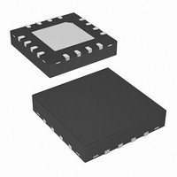
IC PWM CTRLR BUCK 1PHASE 16-QFN

ISL8104IRZ

Manufacturer Part Number
ISL8104IRZ
Description
IC PWM CTRLR BUCK 1PHASE 16-QFN
Manufacturer
Intersil
Datasheet

Specifications of ISL8104IRZ

Pwm Type
Voltage Mode
Number Of Outputs
1
Frequency - Max
1.5MHz
Duty Cycle
100%
Voltage - Supply
7.6 V ~ 15.4 V
Buck
Yes
Boost
No
Flyback
No
Inverting
No
Doubler
No
Divider
No
Cuk
No
Isolated
No
Operating Temperature
-40°C ~ 85°C
Package / Case
16-VQFN Exposed Pad, 16-HVQFN, 16-SQFN, 16-DHVQFN
Frequency-max
1.5MHz
Input Voltage
15.4V
Output Voltage
5V
Frequency
1.5MHz
Supply Voltage Range
8V To 14V
Digital Ic Case Style
QFN
No. Of Pins
16
Operating Temperature Range
-40°C To +85°C
Filter Terminals
SMD
Rohs Compliant
Yes
Controller Type
PWM
Lead Free Status / RoHS Status
Lead free / RoHS Compliant
8V to 14V, Single-Phase Synchronous
Buck Pulse-Width Modulation (PWM)
Controller With Integrated Gate Drivers
The ISL8104 is a 8V to 14V synchronous PWM controller
with integrated MOSFET drivers. The controller features the
ability to safely start-up into prebiased output loads and
provides protection against overcurrent fault events.
Overcurrent protection is implemented using top-side
MOSFET r
sensing resistor.
The ISL8104 employs voltage-mode control with dual-edge
modulation to achieve fast transient response. The operating
frequency is adjustable from 50kHz to 1.5MHz with full (0%
to 100%) PWM duty cycle capability. The error amplifier
features a 15MHz (typ) gain-bandwidth product and 6V/µs
slew rate enabling high converter bandwidth.
The output voltage of the converter can be regulated to as
low as 0.597V with a tolerance of ±1.0% over the
commercial temperature range (0°C to +70°C), and ±1.5%
over industrial temperature range (-40°C to +85°C).
Provided in the QFN package, a SS pin and REFIN pin
enable supply sequencing and voltage tracking functionality.
Pinouts
DS(ON)
COMP
COMP
TSOC
FSET
EN
GND
SS
FB
EN
SS
FB
sensing, eliminating the need for a current
1
2
3
4
1
2
3
4
5
6
7
ISL8104 (14 LD SOIC)
ISL8104 (16 LD QFN)
16
5
TOP VIEW
TOP VIEW
15
®
6
1
14
7
13
Data Sheet
8
14
13
12
11
10
9
8
12
11
10
9
VCC
PVCC
BGATE
PGND
BOOT
TGATE
LX
PVCC
BGATE
PGND
BOOT
1-888-INTERSIL or 1-888-468-3774
CAUTION: These devices are sensitive to electrostatic discharge; follow proper IC Handling Procedures.
Features
• +8V ±5% to +14V ±10% Bias Voltage Range
• 0.597V Internal Reference Voltage
• Voltage-Mode PWM Control with Dual-Edge Modulation
• 14V High Speed N-Channel MOSFET Gate Drivers
• Fast Transient Response
• Programmable Operating Frequency from 50kHz to
• Lossless Programmable Overcurrent Protection
• Sourcing and Sinking Current Capability
• Support for Start-Up into Prebiased Loads
• Soft-Start Done and an External Reference Pin for
• Pb-free available (RoHS compliant)
Applications
• Test and Measurement Instruments
• Distributed DC/DC Power Architecture
• Industrial Applications
• Telecom/Datacom Applications
Ordering Information
ISL8104CBZ*
ISL8104IBZ*
ISL8104CRZ*
ISL8104IRZ*
ISL8104EVAL1Z Evaluation Board
ISL8104EVAL2Z Evaluation Board
*Add “-T” suffix for tape and reel. Please refer to TB347 for details on
reel specifications.
NOTE: These Intersil Pb-free plastic packaged products employ
special Pb-free material sets; molding compounds/die attach materials
and 100% matte tin plate PLUS ANNEAL - e3 termination finish, which
is RoHS compliant and compatible with both SnPb and Pb-free
soldering operations. Intersil Pb-free products are MSL classified at
Pb-free peak reflow temperatures that meet or exceed the Pb-free
requirements of IPC/JEDEC J STD-020.
PART NUMBER
- 1.5V to 15.4V Input Voltage Range
- ±1.0% Over the Commercial Temperature Range
- ±1.5% Over the Industrial Temperature Range
- 2.0A Source/3A Sink at 14V Bottom-Side Gate Drive
- 1.25A Source/2A Sink at 14V Top-Side Gate Drive
- 15MHz (typ) Gain-Bandwidth Error Amplifier with 6V/µs
- Full 0% to 100% Duty Cycle Support
1.5MHz
- Top-Side MOSFET’s r
- ~120ns Blanking Time
Tracking Applications are Available in the QFN Package
slew rate
(Note)
All other trademarks mentioned are the property of their respective owners.
March 7, 2008
|
Intersil (and design) is a registered trademark of Intersil Americas Inc.
Copyright Intersil Americas Inc. 2006, 2007. All Rights Reserved
8104CBZ
8104IBZ
81 04CRZ
81 04IRZ
MARKING
PART
DS(ON)
RANGE (°C)
-40 to +85
-40 to +85
0 to +70
0 to +70
TEMP.
Sensing
16 Ld 4x4 QFN L16.4x4
14 Ld SOIC
14 Ld SOIC
PACKAGE
ISL8104
(Pb-free)
FN9257.2
M14.15
M14.15
DWG. #
PKG.

Related parts for ISL8104IRZ

ISL8104IRZ Summary of contents

Page 1

... PGND 10 PART NUMBER BOOT 9 (Note) ISL8104CBZ* ISL8104IBZ* ISL8104CRZ* ISL8104IRZ* ISL8104EVAL1Z Evaluation Board ISL8104EVAL2Z Evaluation Board VCC *Add “-T” suffix for tape and reel. Please refer to TB347 for details on PVCC reel specifications. NOTE: These Intersil Pb-free plastic packaged products employ BGATE special Pb-free material sets ...

Page 2

Block Diagram EN SSDONE (QFN ONLY) FSET 6µA REFERENCE V = 0.597 V REF REFIN (QFN ONLY) GND SS VCC INTERNAL REGULATOR POWER-ON RESET (POR) 30μA SOFT-START AND FAULT LOGIC OSCILLATOR EA COMP FB TSOC 200µA BOOT SOURCE OCP TGATE ...

Page 3

Typical Application with Single Power Supply +8V TO +14V FILTER C F1 SSDONE (QFN ONLY) REFIN (QFN ONLY FSET FSET Typical Application with Separated Power Supplies +8V TO +14V V R FILTER ...

Page 4

... Thermal Resistance (Typical) SOIC Package (Note QFN Package (Notes 2, 3 Maximum Junction Temperature . . . . . . . . . . . . . . . . . . . . . +150°C Maximum Storage Temperature Range . . . . . . . . . .-65°C to +150°C - 16V 0.3V Pb-free reflow profile . . . . . . . . . . . . . . . . . . . . . . . . . .see link below BOOT http://www.intersil.com/pbfree/Pb-FreeReflow.asp PVCC SYMBOL TEST CONDITIONS I SS/ VCC I SS/ PVCC T = 0° ...

Page 5

Electrical Specifications Recommended Operating Conditions, unless otherwise noted, specifications in bold are valid for process, temperature, and line operating conditions. (Continued) PARAMETER OSCILLATOR Trim Test Frequency Total Variation (Note 4) Ramp Amplitude Ramp Bottom (Note 4) ERROR AMPLIFIER DC Gain ...

Page 6

LX (Pin 7/8) This pin connects to the source of the top-side MOSFET and the drain of the bottom-side MOSFET. This pin represents the return path for the top-side gate driver. During normal switching, this pin is used for top-side ...

Page 7

GND to VREF (0.597V nominal). If the ISL8104 is utilizing an externally supplied reference, when the voltage on the SS pin reaches 1V, the internal reference input (into the error amp) ramps ...

Page 8

... SW High Speed MOSFET Gate Driver The integrated driver has the same drive capability and feature as the Intersil’s 12V gate driver, ISL6612. The PWM tri-state feature helps prevent a negative transient on the output voltage when the output is being shut down. This eliminates the Schottky diode that is used in some systems for protecting the loads from reversed-output-voltage damage ...

Page 9

The power plane should support the input power and output power nodes. Use copper filled polygons on the top and bottom circuit layers for the LX nodes. Use the remaining printed circuit layers for small signal wiring. Locate the ISL8104 ...

Page 10

SW SW regulator. Change the numerical factor (0.7) below to reflect desired placement of this pole. Placement of F lower in frequency helps reduce the gain of the compensation network ...

Page 11

Unfortunately, ESL is not a specified parameter. Work with your capacitor supplier and measure the capacitor’s impedance with frequency to select a suitable component. In most cases, multiple electrolytic capacitors of small case size perform better than a ...

Page 12

Standard-gate MOSFETs are normally recommended for use with the ISL8104. However, logic-level gate MOSFETs can be used under special circumstances. The input voltage, top-side gate drive level, and the MOSFETs absolute gate- to-source voltage rating determine whether logic-level MOSFETs are ...

Page 13

Small Outline Plastic Packages (SOIC) N INDEX 0.25(0.010) H AREA E - SEATING PLANE - -C- α 0.10(0.004) 0.25(0.010 NOTES: 1. Symbols are defined in the ...

Page 14

... Accordingly, the reader is cautioned to verify that data sheets are current before placing orders. Information furnished by Intersil is believed to be accurate and reliable. However, no responsibility is assumed by Intersil or its subsidiaries for its use; nor for any infringements of patents or other rights of third parties which may result from its use ...

Related keywords