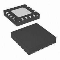
ISL8104IRZ Intersil, ISL8104IRZ Datasheet - Page 5

ISL8104IRZ
Manufacturer Part Number
ISL8104IRZ
Description
IC PWM CTRLR BUCK 1PHASE 16-QFN
Manufacturer
Intersil
Datasheet
1.ISL8104IBZ.pdf
(14 pages)
Specifications of ISL8104IRZ
Pwm Type
Voltage Mode
Number Of Outputs
1
Frequency - Max
1.5MHz
Duty Cycle
100%
Voltage - Supply
7.6 V ~ 15.4 V
Buck
Yes
Boost
No
Flyback
No
Inverting
No
Doubler
No
Divider
No
Cuk
No
Isolated
No
Operating Temperature
-40°C ~ 85°C
Package / Case
16-VQFN Exposed Pad, 16-HVQFN, 16-SQFN, 16-DHVQFN
Frequency-max
1.5MHz
Input Voltage
15.4V
Output Voltage
5V
Frequency
1.5MHz
Supply Voltage Range
8V To 14V
Digital Ic Case Style
QFN
No. Of Pins
16
Operating Temperature Range
-40°C To +85°C
Filter Terminals
SMD
Rohs Compliant
Yes
Controller Type
PWM
Lead Free Status / RoHS Status
Lead free / RoHS Compliant
Electrical Specifications
Functional Pin Description (QFN/SOIC)
SS (Pin 1/3)
Connect a capacitor from this pin to ground. This capacitor,
along with an internal 30µA current source, sets the soft-start
interval of the converter.
COMP (Pin 2/4) and FB (Pin 3/5)
COMP and FB are the available external pins of the error
amplifier. The FB pin is the inverting input of the error
amplifier and the COMP pin is the error amplifier output.
These pins are used to compensate the voltage-control
feedback loop of the converter.
OSCILLATOR
Trim Test Frequency
Total Variation (Note 4)
Ramp Amplitude
Ramp Bottom (Note 4)
ERROR AMPLIFIER
DC Gain (Note 4)
Gain-Bandwidth Product (Note 4)
Slew Rate (Note 4)
COMP Source Current (Note 4)
COMP Sink Current (Note 4)
GATE DRIVERS
Top-side Drive Source Current (Note 4)
Top-side Drive Source Impedance
Top-side Drive Sink Current (Note 4)
Top-side Drive Sink Impedance
Bottom-side Drive Source Current (Note 4)
Bottom-side Drive Source Impedance
Bottom-side Drive Sink Current (Note 4)
Bottom-side Drive Sink Impedance
PROTECTION
TSOC Current
TSOC Measurement Offset (Note 4)
SOFT-START
Soft-start Current
SSDONE Low Output Voltage (QFN ONLY)
PARAMETER
5
Recommended Operating Conditions, unless otherwise noted, specifications in bold are valid for process,
temperature, and line operating conditions. (Continued)
R
OCP
R
I COMPSRC
I COMPSNK
I
I
T_SOURCE
B_SOURCE
SYMBOL
T_SOURCE
B_SOURCE
R
R
I
I
ΔV
GBWP
T_SINK
B_SINK
I
T_SINK
B_SINK
TSOC
I
SR
OFFSET
SS
OSC
8kΩ < R
R
R
R
R
R
V
90mA Source Current
V
90mA Source Current
V
90mA Source Current
V
90mA Source Current
T
T
TSOC = 1.5V to 15.4V
I
SSDONE
J
J
FSET
FSET
L
L
L
BOOT
BOOT
PVCC
PVCC
= 0°C to +70°C
= -40°C to +85°C
= 10kΩ, C
= 10kΩ, C
= 10kΩ, C
ISL8104
= OPEN V
= OPEN
= 14V, 3nF Load
= 14V, 3nF Load
- V
- V
FSET
= 2mA
TEST CONDITIONS
LX
LX
L
L
L
= 14V, 3nF Load
= 14V, 3nF Load
to GND < 200kΩ
= 100pF
= 100pF
= 100pF
VCC
EN (Pin 4/6)
This pin is a TTL compatible input. Pull this pin below 0.8V to
disable the converter. In shutdown the soft-start pin is
discharged and the TGATE and BGATE pins are held low.
REFIN (QFN ONLY Pin 5)
Upon enable if REFIN is less than 2.2V, the external
reference pin is used as the control reference instead of the
internal 0.597V reference. An internal 6µA pull-up to 5V is
provided for disabling this functionality.
GND (Pin 6/7)
Signal ground for the IC. All voltage levels are measured
with respect to this pin.
= 12
MIN
175
180
176
1.7
22
-
-
-
-
-
-
-
-
-
-
-
-
-
-
-
-
-
TYP
1.25
0.94
200
±15
200
200
±10
1.9
2.0
1.3
1.3
88
15
30
1
6
2
2
2
2
3
-
MAX
2.15
0.30
220
220
224
38
-
-
-
-
-
-
-
-
-
-
-
-
-
-
-
-
March 7, 2008
UNITS
V
MHz
V/μs
kHz
mA
mA
mV
FN9257.2
dB
μA
μA
μA
%
P-P
Ω
Ω
Ω
Ω
V
A
A
A
A
V


