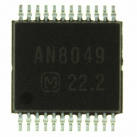
AN8049SH-E1 Panasonic - SSG, AN8049SH-E1 Datasheet - Page 16

AN8049SH-E1
Manufacturer Part Number
AN8049SH-E1
Description
IC MULTI CONFIG 40MA SSOP24D
Manufacturer
Panasonic - SSG
Type
Step-Down (Buck), Step-Up (Boost), Invertingr
Specifications of AN8049SH-E1
Internal Switch(s)
Yes
Synchronous Rectifier
No
Number Of Outputs
3
Current - Output
40mA
Frequency - Switching
20kHz ~ 1MHz
Voltage - Input
1.8 ~ 14 V
Operating Temperature
-30°C ~ 85°C
Mounting Type
Surface Mount
Package / Case
24-SSOP
Power - Output
146mW
Lead Free Status / RoHS Status
Contains lead / RoHS non-compliant
Voltage - Output
-
Other names
AN8049SHE1
AN8049SHE1TR
AN8049SHE1TR
Available stocks
Company
Part Number
Manufacturer
Quantity
Price
Company:
Part Number:
AN8049SH-E1V
Manufacturer:
MITSUMI
Quantity:
2 511
Part Number:
AN8049SH-E1V
Manufacturer:
PANASONIC/松下
Quantity:
20 000
AN8049FHN
I Application Notes (continued)
16
[4] Function descriptions (continued)
[5] Time constant setup for the timer latch short-circuit protection circuit
10. Output 3 block
11. CTL block
comparator continuously compares a 0.9 V reference voltage with the FB1, FB2, and FB3 error amplifier outputs.
average value since there are no fluctuations in the error amplifier outputs. At this time, the output transistor Q1 will
be in the conducting state, and the S.C.P. pin will be held at 0 V.
protection comparator from the error amplifier output, the short-circuit protection comparator will output a low level
and the output transistor Q1 will shut off. Then, the capacitor C
the external capacitor C
latch and the dead-time will be set to 100% with the output held fixed at the low level. Once the latch circuit has
latched, the S.C.P. pin capacitor will be discharged to about 0 V, but the latch circuit will not reset unless either power
is turned off or the power supply is restarted using on/off control.
state, and the IC starts to charge the S.C.P. pin capacitor. Therefore,
users must select an external capacitor that allows the DC-DC con-
verter output voltage to rise before the latch circuit in the later stage
latches. In particular, care is required if the soft start function is used,
since that function makes the startup time longer.
9. Output 1 and output 2 blocks
can be set up freely by connecting current setting resistors to the RB pins.
regulation can be set up freely by connecting current setting resistors to the RB2 pin.
Figure 6 shows the structure of the timer latch short-circuit protection circuit. The short-circuit protection
When the DC-DC converter output load conditions are stable, the short-circuit protection comparator holds its
If the output load conditions change rapidly and a high-level signal (0.9 V or higher) is input to the short-circuit
At power supply startup, the output appears to be in the shorted
1.26 V = I
∴ t
These output circuits have a totem pole structure. A constant-current source output with good line regulation
These circuits can provide a constant-current source output of up to 50 mA.
This output circuit has an open collector structure.
An output current of up to 50 mA can be provided, and the output pin has a breakdown voltage of 15 V.
The CTL block output circuit also has a totem pole structure. A constant-current source output with good line
The CTL block can provide a constant-current source output of up to 50 mA.
PE
FB1
FB2
FB3
(s) = 1.15 × C
CHG
22
20
18
×
C
t
PE
SCP
SCP
SCP
On/off control
is charged to about 1.26 V by the constant current of about 1.1 mA, the latch circuit will
(µF)
S.C.P. comp.
0.9 V
Figure 6. Short-circuit protection circuit
Q1
V
CC
SDH000011BEB
1.1 µA
S.C.P.
High level detection comparator
1.26 V
SCP
connected to the S.C.P. pin will start to charge. When
Latch
U.V.L.O.
R
S
1.26
V
Q
SCP
0
Figure 5. S.C.P. pin charging waveform
(V)
Short-circuit detection time t
V
REF
Output shutoff
PE
t (s)


