XCL206B283AR-G Torex Semiconductor Ltd, XCL206B283AR-G Datasheet - Page 10
XCL206B283AR-G
Manufacturer Part Number
XCL206B283AR-G
Description
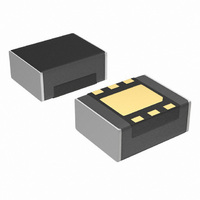
IC BUCK SYNC 2.8V 0.6A USP-6EL
Manufacturer
Torex Semiconductor Ltd
Series
XCL206r
Type
Point of Load (POL) Non-Isolated with UVLOr
Datasheet
1.XCL206B123AR-G.pdf
(27 pages)
Specifications of XCL206B283AR-G
Output
2.8V
Number Of Outputs
1
Power (watts)
1W
Mounting Type
Surface Mount
Voltage - Input
2 ~ 6 V
Package / Case
USP-6EL
1st Output
2.8 VDC @ 600mA
Size / Dimension
0.10" L x 0.08" W x 0.04" H (2.5mm x 2.0mm x 1.04mm)
Power (watts) - Rated
1W
Operating Temperature
-40°C ~ 85°C
Efficiency
90%
Current - Output
600mA
Voltage - Output
2.8V
Power - Output
1W
Internal Switch(s)
Yes
Frequency - Switching
3MHz
Synchronous Rectifier
Yes
For Use With
893-1159 - BOARD EVAL XCL206B283AR-G 2.8V
Lead Free Status / RoHS Status
Lead free / RoHS Compliant
Other names
893-1151-2


■ELECTRICAL CHARACTERISTICS (Continued)
10/27
Lx SW "H" Leakage Current
Supply Current (XCL206, XCL207)
●XCL205G1K3AR/XCL206G1K3AR/XCL207G1K3AR, V
PFM Switching Current
PWM "H" Level Voltage
PWM "H" Level Voltage
Test conditions: Unless otherwise stated, V
NOTE:
Supply Current (XCL205)
Lx SW "H" ON Resistance 1
Lx SW "H" ON Resistance 2
Temperature Characteristics
Lx SW "L" ON Resistance 1
Lx SW "L" ON Resistance 2
Allowed Inductor Current
Operating Voltage Range
Maximum Output Current
Oscillation Frequency
Maximum Duty Cycle
Minimum Duty Cycle
XCL205/XCL206/XCL207
PFM Duty Limit
*3: ON resistance (Ω)= (V
*4: Design value
*5: When temperature is high, a current of approximately 10μA (maximum) may leak.
*1: Including hysteresis operating voltage range.
*2: EFFI = { ( output voltage×output current ) / ( input voltage×input current) }×100
Threshold Voltage
*6: The CE/MODE pin of the XCL207 series works also as an external switching pin of PWM control and PWM/PFM control. When the IC is in the
*7: Time until it short-circuits V
*8: When V
*9: When the difference between the input and the output is small, some cycles may be skipped completely before current maximizes.
*10: Current limit denotes the level of detection at peak of coil current.
*11: “H”=V
*12: I
*13: V
*14:
Stand-by Current
Inductance Value
Current Limit
Short Protection
CE "H" Voltage
CE "H" Current
Output Voltage
Output Voltage
CE "L" Voltage
CE "L" Current
Soft Start Time
UVLO Voltage
PARAMETER
CL Discharge
operation, control is switched to the automatic PWM/PFM switching mode when the CE/MODE pin voltage is equal to or greater than V
0.3V, and to the PWM mode when the CE/MODE pin voltage is equal to or lower than V
If current is further pulled from this state, output voltage will decrease because of P-ch driver ON resistance.
Efficiency
Latch Time
V
PFM
IN
PWMH
is applied when V
and DTY
IN
IN
~V
and V
(*2)
is less than 2.4V, limit current may not be reached because voltage falls caused by ON resistance.
IN
(*10)
(*12)
-1.2V, “L”=+0.1V~-0.1V
PWML
LIMIT_PFM
(*13)
(*13)
(*12)
(*5)
are defined only for the XCL207 series. (They are not used in the XCL205/and XCL206 series)
OUT (T)
IN
(V
are defined only for the XCL206 and XCL207 series which have PFM control function. (Not for the XCL 205 series)
DTY
SYMBOL
MAXDTY
MINDTY
OUT
- Lx pin measurement voltage) / 100mA
x 0.5V becomes more than V
I
△V
OUT
V
V
V
R
OUTMAX
V
I
EFFI
R
R
R
R
V
V
LEAKH
V
f
・△Topr)
I
I
I
I
SHORT
I
PWMH
t
V
I
LIMIT_PFM
PWML
I
UVLO
OSC
PFM
CEH
t
DCHG
STB
CEL
LIM
LAT
OUT
DD
L x H
L x H
L x L
L x L
CEH
DC
CEL
SS
L
IN
OUT
with GND via 1Ωof resistor from an operational state and is set to Lx=0V from current limit pulse generating.
/
IN
=5.0V, V
level within 1ms
When connected to external components,
V
V
When connected to external components
V
Voltage which Lx pin holding “L” level
V
V
When connected to external components,
V
When connected to external components,
V
V
V
V
When connected to external components,
V
V
V
V
V
V
V
I
-40℃≦Topr≦85℃
V
Voltage changes Lx to “H” level
V
Voltage changes Lx to “L” level
When connected to external components,
I
frequency becomes 2550kHz≦f
When connected to external components,
I
frequency becomes f
V
V
When connected to external components,
V
V
Short Lx at 1Ω resistance
Sweeping V
1Ω resistance, V
V
Test frequency=1MHz
ΔT=40℃
OUT
OUT
OUT
IN
IN
CE
IN
IN
IN
IN
CE
IN
IN
CE
IN
IN
IN
IN
IN
IN
OUT
OUT
IN
IN
CE
IN
IN
=V
= V
=V
=V
= V
=0V→V
= V
=V
=5.0V, V
=V
=V
= V
= V
= V
= V
= V
= V
= V
=1mA
=1mA
= V
=5.0V, V
= 5.0V L
= V
=30mA
=0V, Applied voltage to V
=0V, Applied voltage to V
OUT (T)
OUT(T)
CE
IN
CE
OUT(T)
OUT(T)
OUT
CE
IN
CE
CE
CE
CE
CE
CE
CE
CE
IN
,V
=5.0V, V
=5.0V, V
= V
= 5.0V, V
=5.0V, I
=5.0V, V
=5.0V, V
= 5.0V, V
= 3.6V, V
= 5.0V
= 3.6V
=5.0V, V
OUT(T)
=5.0V, V
= V
(*6),
(*6)
+2.0V, V
+2.0V,V
+2.0V, V
IN
= Nominal Voltage
CE
CE
OUT
OUT(T)
, Voltage which oscillation
IN
Voltage which oscillation
, I
X
.
=0V, V
×0.5V
= 0V, V
OUT (T)
, V
OUT
= 5.0V V
OUT
(*4)
(*4)
OUT
OUT
+1.0V, I
IN
OUT
Series
CONDITIONS
OUT
OUT
OUT
OUT
=1mA
CE
OUT
OUT
CE
CE
OUT
=0.8×V
=V
CE
= V
+1.2V, I
OUT
=30mA
OSC
=1.0V
=1.0V, I
=0V, L
voltage which Lx becomes “L”
(*14)
= V
= V
= V
= 0V
OUT
CE
= V
= 0V,IL
= 0V,IL
=1.75V, f
OUT(T)
= V
CE
<2550kHz
=5.0V, Short Lx at
,
OUT
OUT (T)
OUT (T)
OUT (T)
= 0V
IN
= 0V V
OUT(T)
(*7)
X
OUT(T)
, I
OUT
×1.1V
=1mA
=0V
OUT
X
X
OUT
CE
CE
×0.9V
×1.1V
×0.9V
= 100mA
= 100mA
= 100mA
=100mA
,
,
(*11)
×1.1V
(*11)
OSC
=1mA
OSC
OUT
≦3450kHz
(*13)
=3.0MHz, Ta=25℃
= open
(*1, *11)
(*8)
(*3)
(*3)
(*9)
IN
minus 1.0V and equal to or greater than V
(*13)
1.715
0.329
MIN.
2550
- 0.1
- 0.1
1.00
0.65
V
0.25
600
170
100
900
200
1.8
V
1.0
IN
-
-
-
-
-
-
-
-
-
-
-
-
-
-
-
-
SS
-
±100
0.438
3000
1050
1000
TYP.
1.750
1.40
0.35
0.42
0.45
0.52
0.01
0.25
220
200
300
1.5
46
21
85
0
-
-
-
-
-
-
-
-
-
-
-
V
1.785
0.548
MAX.
3450
1350
IN
1.78
0.55
0.67
0.66
0.77
0.25
0.40
270
300
450
6.0
1.0
1.0
6.0
0.1
0.1
65
35
20
0
-
-
-
-
- 1.0
-
-
-
ppm/ ℃
UNITS CIRCUIT
μA
μA
kHz
μA
μA
μA
μH
mA
mA
mA
mA
ms
ms
Ω
Ω
Ω
Ω
Ω
%
%
%
%
V
V
V
V
V
V
V
V
CEH
.
IN
minus
①
①
①
③
②
②
①
⑩
①
③
③
①
④
④
⑨
⑥
①
③
③
①
①
⑤
⑤
①
⑦
⑦
⑧
-
-
-
-
Related parts for XCL206B283AR-G
Image
Part Number
Description
Manufacturer
Datasheet
Request
R

Part Number:
Description:
BOARD EVAL XCL206B153AR-G 1.5V
Manufacturer:
Torex Semiconductor Ltd
Datasheet:

Part Number:
Description:
BOARD EVAL XCL206B123AR-G 1.2V
Manufacturer:
Torex Semiconductor Ltd
Datasheet:
Part Number:
Description:
BOARD EVAL XCL206B303AR-G 3.0V
Manufacturer:
Torex Semiconductor Ltd
Datasheet:
Part Number:
Description:
BOARD EVAL XCL206B183AR-G 1.8V
Manufacturer:
Torex Semiconductor Ltd
Datasheet:

Part Number:
Description:
IC BUCK SYNC 1.2V 0.6A USP-6EL
Manufacturer:
Torex Semiconductor Ltd
Datasheet:
Part Number:
Description:
IC BUCK SYNC 1.5V 0.6A USP-6EL
Manufacturer:
Torex Semiconductor Ltd
Datasheet:
Part Number:
Description:
IC BUCK SYNC 1.8V 0.6A USP-6EL
Manufacturer:
Torex Semiconductor Ltd
Datasheet:
Part Number:
Description:
IC BUCK SYNC 3V 0.6A USP-6EL
Manufacturer:
Torex Semiconductor Ltd
Datasheet:
Part Number:
Description:
BOARD EVAL XCL206B283AR-G 2.8V
Manufacturer:
Torex Semiconductor Ltd
Datasheet:
Part Number:
Description:
DUAL DC/DC CONVERT CONTROL 10PIN
Manufacturer:
Torex Semiconductor Ltd
Datasheet:

Part Number:
Description:
IC SUPERVISOR 3V SOT23-3
Manufacturer:
Torex Semiconductor Ltd
Datasheet:
Part Number:
Description:
IC SUPERVISOR 1.8V SOT23-3
Manufacturer:
Torex Semiconductor Ltd
Datasheet:
Part Number:
Description:
IC SUPERVISOR 2V SOT23-3
Manufacturer:
Torex Semiconductor Ltd
Datasheet:
Part Number:
Description:
IC SUPERVISOR 2.7V SOT23-3
Manufacturer:
Torex Semiconductor Ltd
Datasheet:
Part Number:
Description:
IC SUPERVISOR 2.8V SOT23-3
Manufacturer:
Torex Semiconductor Ltd
Datasheet: