XCL206B283AR-G Torex Semiconductor Ltd, XCL206B283AR-G Datasheet - Page 12
XCL206B283AR-G
Manufacturer Part Number
XCL206B283AR-G
Description
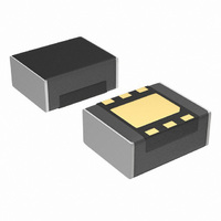
IC BUCK SYNC 2.8V 0.6A USP-6EL
Manufacturer
Torex Semiconductor Ltd
Series
XCL206r
Type
Point of Load (POL) Non-Isolated with UVLOr
Datasheet
1.XCL206B123AR-G.pdf
(27 pages)
Specifications of XCL206B283AR-G
Output
2.8V
Number Of Outputs
1
Power (watts)
1W
Mounting Type
Surface Mount
Voltage - Input
2 ~ 6 V
Package / Case
USP-6EL
1st Output
2.8 VDC @ 600mA
Size / Dimension
0.10" L x 0.08" W x 0.04" H (2.5mm x 2.0mm x 1.04mm)
Power (watts) - Rated
1W
Operating Temperature
-40°C ~ 85°C
Efficiency
90%
Current - Output
600mA
Voltage - Output
2.8V
Power - Output
1W
Internal Switch(s)
Yes
Frequency - Switching
3MHz
Synchronous Rectifier
Yes
For Use With
893-1159 - BOARD EVAL XCL206B283AR-G 2.8V
Lead Free Status / RoHS Status
Lead free / RoHS Compliant
Other names
893-1151-2


■OPERATIONAL DESCRIPTION
The XCL205/XCL/206/XCL207 series consists of a reference voltage source, ramp wave circuit, error amplifier, PWM
comparator, phase compensation circuit, output voltage adjustment resistors, P-channel MOSFET driver transistor, N-channel
MOSFET switching transistor for the synchronous switch, current limiter circuit, UVLO circuit with control IC, and an inductor.
(See the block diagram above.) Using the error amplifier, the voltage of the internal voltage reference source is compared with
the feedback voltage from the V
error amplifier output, to input a signal to the PWM comparator to determine the turn-on time during PWM operation. The PWM
comparator compares, in terms of voltage level, the signal from the error amplifier with the ramp wave from the ramp wave circuit,
and delivers the resulting output to the buffer driver circuit to cause the Lx pin to output a switching duty cycle. This process is
continuously performed to ensure stable output voltage. The current feedback circuit monitors the P-channel MOS driver
transistor current for each switching operation, and modulates the error amplifier output signal to provide multiple feedback
signals. This enables a stable feedback loop even when a low ESR capacitor such as a ceramic capacitor is used ensuring
stable output voltage.
<Reference Voltage Source>
The reference voltage source provides the reference voltage to ensure stable output voltage of the DC/DC converter.
<Ramp Wave Circuit>
The ramp wave circuit determines switching frequency. The frequency is fixed internally 3.0MHz. Clock pulses generated in
this circuit are used to produce ramp waveforms needed for PWM operation, and to synchronize all the internal circuits.
<Error Amplifier>
The error amplifier is designed to monitor output voltage. The amplifier compares the reference voltage with the feedback
voltage divided by the internal split resistors, R1 and R2. When a feed back voltage is lower than the reference voltage, the
output voltage of the error amplifier is increased. The gain and frequency characteristics of the error amplifier output are fixed
internally to deliver an optimized signal to the mixer.
<Current Limit>
The current limiter circuit of the XCL205/XCL206/XCL207 series monitors the current flowing through the P-channel MOS driver
transistor connected to the Lx pin, and features a combination of the current limit mode and the operation suspension mode.
① When the driver current is greater than a specific level, the current limit function operates to turn off the pulses from the Lx pin
② When the driver transistor is turned off, the limiter circuit is then released from the current limit detection state.
③ At the next pulse, the driver transistor is turned on. However, the transistor is immediately turned off in the case of an over
④ When the over current state is eliminated, the IC resumes its normal operation.
The IC waits for the over current state to end by repeating the steps ① through ③. If an over current state continues for a few
milliseconds and the above three steps are repeatedly performed, the IC performs the function of latching the OFF state of the
driver transistor, and goes into operation suspension state. Once the IC is in suspension state, operations can be resumed by
either turning the IC off via the CE/MODE pin, or by restoring power to the V
complete shutdown, but a state in which pulse output is suspended; therefore, the internal circuitry remains in operation. The
current limit of the XCL205/XCL206/XCL207 series can be set at 1050mA at typical. Depending on the state of the PC Board,
latch time may become longer and latch operation may not work. In order to avoid the effect of noise, an input capacitor is
placed as close to the IC as possible.
12/27
at any given timing.
current state.
XCL205/XCL206/XCL207
V
V
V
I
Lx
OUT
Lx
CE
IN
OUT
pin through split resistors, R1 and R2. Phase compensation is performed on the resulting
Limit < # ms
Series
Limit > # ms
IN
pin. The suspension state does not mean a
Current Limit LEVEL
Restart
0mA
Vss
Related parts for XCL206B283AR-G
Image
Part Number
Description
Manufacturer
Datasheet
Request
R

Part Number:
Description:
BOARD EVAL XCL206B153AR-G 1.5V
Manufacturer:
Torex Semiconductor Ltd
Datasheet:

Part Number:
Description:
BOARD EVAL XCL206B123AR-G 1.2V
Manufacturer:
Torex Semiconductor Ltd
Datasheet:
Part Number:
Description:
BOARD EVAL XCL206B303AR-G 3.0V
Manufacturer:
Torex Semiconductor Ltd
Datasheet:
Part Number:
Description:
BOARD EVAL XCL206B183AR-G 1.8V
Manufacturer:
Torex Semiconductor Ltd
Datasheet:

Part Number:
Description:
IC BUCK SYNC 1.2V 0.6A USP-6EL
Manufacturer:
Torex Semiconductor Ltd
Datasheet:
Part Number:
Description:
IC BUCK SYNC 1.5V 0.6A USP-6EL
Manufacturer:
Torex Semiconductor Ltd
Datasheet:
Part Number:
Description:
IC BUCK SYNC 1.8V 0.6A USP-6EL
Manufacturer:
Torex Semiconductor Ltd
Datasheet:
Part Number:
Description:
IC BUCK SYNC 3V 0.6A USP-6EL
Manufacturer:
Torex Semiconductor Ltd
Datasheet:
Part Number:
Description:
BOARD EVAL XCL206B283AR-G 2.8V
Manufacturer:
Torex Semiconductor Ltd
Datasheet:
Part Number:
Description:
DUAL DC/DC CONVERT CONTROL 10PIN
Manufacturer:
Torex Semiconductor Ltd
Datasheet:

Part Number:
Description:
IC SUPERVISOR 3V SOT23-3
Manufacturer:
Torex Semiconductor Ltd
Datasheet:
Part Number:
Description:
IC SUPERVISOR 1.8V SOT23-3
Manufacturer:
Torex Semiconductor Ltd
Datasheet:
Part Number:
Description:
IC SUPERVISOR 2V SOT23-3
Manufacturer:
Torex Semiconductor Ltd
Datasheet:
Part Number:
Description:
IC SUPERVISOR 2.7V SOT23-3
Manufacturer:
Torex Semiconductor Ltd
Datasheet:
Part Number:
Description:
IC SUPERVISOR 2.8V SOT23-3
Manufacturer:
Torex Semiconductor Ltd
Datasheet: