BD95500MUV-E2 Rohm Semiconductor, BD95500MUV-E2 Datasheet - Page 18
BD95500MUV-E2
Manufacturer Part Number
BD95500MUV-E2
Description
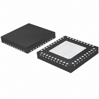
IC BUCK ADJ 6A 40VQFN
Manufacturer
Rohm Semiconductor
Type
Step-Down (Buck)r
Datasheet
1.BD95500MUV-E2.pdf
(20 pages)
Specifications of BD95500MUV-E2
Internal Switch(s)
Yes
Synchronous Rectifier
No
Number Of Outputs
1
Voltage - Output
0.7 ~ 5 V
Current - Output
6A
Frequency - Switching
30kHz ~ 100kHz
Voltage - Input
3 ~ 20 V
Operating Temperature
-10°C ~ 100°C
Mounting Type
Surface Mount
Package / Case
40-VQFN
Power - Output
4.66W
Output Voltage
7 V
Output Current
6 A
Input Voltage
3 V to 20 V
Switching Frequency
200 KHz to 1000 KHz
Operating Temperature Range
- 10 C to + 100 C
Mounting Style
SMD/SMT
Lead Free Status / RoHS Status
Lead free / RoHS Compliant
Other names
BD95500MUV-E2TR


●Operation Notes
(1) Absolute maximum ratings
(2) Connecting the power supply connector backward
(3) Power supply lines
(4) GND voltage
(5) Thermal design
(6) Inter-pin shorts and mounting errors
(7) Actions in strong electromagnetic field
(8) ASO
(9) Thermal shutdown circuit
(10) Testing on application boards
An excess in the absolute maximum ratings, such as supply voltage, temperature range of operating conditions, etc., can
break down the devices, thus making impossible to identify breaking mode, such as a short circuit or an open circuit. If any
over rated values will expect to exceed the absolute maximum ratings, consider adding circuit protection devices, such as
fuses.
Connecting of the power supply in reverse polarity can damage IC. Take precautions when connecting the power supply
lines. An external direction diode can be added.
Design PCB layout pattern to provide low impedance GND and supply lines. To obtain a low noise ground and supply line,
separate the ground section and supply lines of the digital and analog blocks. Furthermore, for all power supply terminals to
ICs, connect a capacitor between the power supply and the GND terminal. When applying electrolytic capacitors in the circuit,
not that capacitance characteristic values are reduced at low temperatures.
The potential of GND pin must be minimum potential in all operating conditions.
Use a thermal design that allows for a sufficient margin in light of the power dissipation (Pd) in actual operating conditions.
Use caution when positioning the IC for mounting on printed circuit boards. The IC may be damaged if there is any
connection error or if pins are shorted together.
Use caution when using the IC in the presence of a strong electromagnetic field as doing so may cause the IC to
malfunction.
When using the IC, set the output transistor so that it does not exceed absolute maximum ratings or ASO.
The IC incorporates a built-in thermal shutdown circuit (TSD circuit). The thermal shutdown circuit (TSD circuit) is designed
only to shut the IC off to prevent thermal runaway. It is not designed to protect the IC or guarantee its operation. Do not
continue to use the IC after operating this circuit or use the IC in an environment where the operation of this circuit is
assumed.
When testing the IC on an application board, connecting a capacitor to a pin with low impedance subjects the IC to stress.
Always discharge capacitors after each process or step. Always turn the IC's power supply off before connecting it to or
removing it from a jig or fixture during the inspection process. Ground the IC during assembly steps as an antistatic measure.
Use similar precaution when transporting or storing the IC.
BD95500MUV
TSD ON Temp. [℃] (typ.)
175
18/20
Hysteresis Temp. [℃] (typ.)
15
Related parts for BD95500MUV-E2
Image
Part Number
Description
Manufacturer
Datasheet
Request
R

Part Number:
Description:
TRANSISTOR, NPN, TO-220
Manufacturer:
SEMELAB
Datasheet:

Part Number:
Description:
Manufacturer:
Rohm Semiconductor
Datasheet:
Part Number:
Description:
Manufacturer:
Rohm Semiconductor
Datasheet:
Part Number:
Description:
Manufacturer:
Rohm Semiconductor
Datasheet:
Part Number:
Description:
Manufacturer:
Rohm Semiconductor
Datasheet:
Part Number:
Description:
Manufacturer:
Rohm Semiconductor
Datasheet:
Part Number:
Description:
Manufacturer:
Rohm Semiconductor
Datasheet:
Part Number:
Description:
Manufacturer:
Rohm Semiconductor
Datasheet:
Part Number:
Description:
Manufacturer:
Rohm Semiconductor
Datasheet:
Part Number:
Description:
Manufacturer:
Rohm Semiconductor
Datasheet:
Part Number:
Description:
Manufacturer:
Rohm Semiconductor
Datasheet:
Part Number:
Description:
Manufacturer:
Rohm Semiconductor
Datasheet:
Part Number:
Description:
Manufacturer:
Rohm Semiconductor
Datasheet: