BD95500MUV-E2 Rohm Semiconductor, BD95500MUV-E2 Datasheet - Page 8
BD95500MUV-E2
Manufacturer Part Number
BD95500MUV-E2
Description
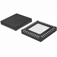
IC BUCK ADJ 6A 40VQFN
Manufacturer
Rohm Semiconductor
Type
Step-Down (Buck)r
Datasheet
1.BD95500MUV-E2.pdf
(20 pages)
Specifications of BD95500MUV-E2
Internal Switch(s)
Yes
Synchronous Rectifier
No
Number Of Outputs
1
Voltage - Output
0.7 ~ 5 V
Current - Output
6A
Frequency - Switching
30kHz ~ 100kHz
Voltage - Input
3 ~ 20 V
Operating Temperature
-10°C ~ 100°C
Mounting Type
Surface Mount
Package / Case
40-VQFN
Power - Output
4.66W
Output Voltage
7 V
Output Current
6 A
Input Voltage
3 V to 20 V
Switching Frequency
200 KHz to 1000 KHz
Operating Temperature Range
- 10 C to + 100 C
Mounting Style
SMD/SMT
Lead Free Status / RoHS Status
Lead free / RoHS Compliant
Other names
BD95500MUV-E2TR


●Pin Descriptions
・VCC (5 Pin)
・EN (39 Pin)
・VDD (14 Pin)
・VREG (7 Pin)
・REF (10 Pin)
・ILIM (4 Pin)
・SS/TRACK (9 Pin)
・VINS (37 Pin)
・FS (8 Pin)
・Is+ (13 pin)、Is- (12 pin)
・BOOT (38 pin)
・PGOOD (1 pin)
・CE (3 pin)
・MODE (40 pin)
・VOUT (11 pin)
・SW (22-29 pin)
・VIN (31-36 pin)
・PGND (15-21, 30 pin)
This is connected pin for coil. SW voltage swings between VIN and GND. It is recommended to connect by heavy and short
pattern to coil.
This is the power supply pin for IC internal circuits, except the FET driver. The input supply voltage range is 4.5V to 5.5V. It
is recommended that a 10Ω/0.1uF C-R filter be put in this pin from VDD rail.
When EN pin voltage is at least 2.3V, the status of this switching regulator becomes active. Conversely, the status switches
off when EN pin voltage goes lower than 0.8V and circuit current becomes 0uA.
This is the power supply pin to drive the LOW side FET and for Boot-strap diode. It is recommended that a 1~10uF bypass
capacitor be established to compensate for rush current during the FET ON/OFF transition.
This is the reference voltage output pin. The voltage is 2.5V, with 500uA current ability. It is recommended that a 0.22~1uF
capacitor (X5R or X7R) be established between VREG and GND (6 Pin). When REF is not adjusted from the external
voltage supply, the REF voltage can be adjusted using the external resistor divider of VREG.
This is the output voltage adjustment pin by resistor divider network from VREG pin (0.7~2.0V). It is also very convenient for
synchronizing external voltage supply. The IC controls the output voltage (REF≒VOUT).
BD95500MUV detects the voltage between Is+ pin and Is- pin and limits the output current (OCP). Voltage equivalent to
1/10 of the ILIM voltage is the voltage drop of external current sense resistor. A very low current sense resistor or inductor
DCR can also be used for this platform.
This is the adjustment pin to set the soft start time. SS voltage is low during standby status. When EN is ON, the soft start
time can be determined by the SS charge current and capacitor between SS-GND. Until SS reaches REF voltage, the
output voltage is equivalent to SS voltage. And also this pin enables to operate tracking function. The output voltage keeps
track of a power supply rail by connecting 10kΩ resistance between the power supply rail and SS/TRACK pin.
The duty cycle is determined by input voltage and controls output voltage. In other words, the output voltage is affected by
input voltage. Therefore, when VINS voltage fluctuates, the output voltage becomes also unstable. Since the VINS line is
also the input voltage of the switching regulator, stability depends on the impedance of the voltage supply. It is
recommended to establish a bypass capacitor or CR filter suitable for the actual application.
This is the pin to adjust the switching frequency with the resistor. It is recommended that a resistor be established to GND (6
pin).The frequency range is from 200kHz to 1000kHz.
These pins are connected to both sides of the current sense resistor to detect output current. The voltage drop between Is+
and Is- is compared with the voltage equivalent to 1/10 of ILIM voltage. When this voltage drop hits the specified voltage
level, the output voltage is OFF. Since the maximum input voltage is 2.7V, set the output voltage by the resistance division
value in case the output voltage is 2.7V or more.
This is the voltage supply to drive the high side FET and a Diode for BOOT strap function is built in. The maximum absolute
ratings are 30V (from GND) and 7V (from SW). BOOT voltage swings between (VIN+Vcc) and Vcc during active operation.
This pin is output pin for Power Good. It is open drain pin and recommended to connect to other power supply through the
pull-up resistance (about 100kΩ).
This pin is for the ceramic capacitor. It is useful to utilize low ESR capacitor for output capacitor.
This is the control mode changeable pin. The status is Low : continuous mode, the status is High : SLLM
This is the monitor pin for output voltage. This IC controls the voltage in the status of REF≒VOUT. When output voltage is
required 2V or more, set the output voltage by the resistance division value.
This is input power supply pin. Recommend input voltage is 3.3V to 20V. Connect the input capacitor against PGND directly.
This is power ground pin. It is recommended to connect by heavy and short pattern. Connect in reverse side of IC when
connecting to GND (6 pin).
8/20
TM
.
Related parts for BD95500MUV-E2
Image
Part Number
Description
Manufacturer
Datasheet
Request
R

Part Number:
Description:
TRANSISTOR, NPN, TO-220
Manufacturer:
SEMELAB
Datasheet:

Part Number:
Description:
Manufacturer:
Rohm Semiconductor
Datasheet:
Part Number:
Description:
Manufacturer:
Rohm Semiconductor
Datasheet:
Part Number:
Description:
Manufacturer:
Rohm Semiconductor
Datasheet:
Part Number:
Description:
Manufacturer:
Rohm Semiconductor
Datasheet:
Part Number:
Description:
Manufacturer:
Rohm Semiconductor
Datasheet:
Part Number:
Description:
Manufacturer:
Rohm Semiconductor
Datasheet:
Part Number:
Description:
Manufacturer:
Rohm Semiconductor
Datasheet:
Part Number:
Description:
Manufacturer:
Rohm Semiconductor
Datasheet:
Part Number:
Description:
Manufacturer:
Rohm Semiconductor
Datasheet:
Part Number:
Description:
Manufacturer:
Rohm Semiconductor
Datasheet:
Part Number:
Description:
Manufacturer:
Rohm Semiconductor
Datasheet:
Part Number:
Description:
Manufacturer:
Rohm Semiconductor
Datasheet: