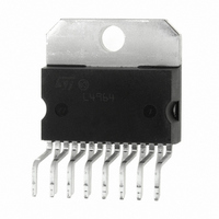
L4964 STMicroelectronics, L4964 Datasheet

L4964
Specifications of L4964
Available stocks
Related parts for L4964
L4964 Summary of contents
Page 1
... Features of the device include overload protection, soft start, remote inhibit, thermal protection, a reset output for microprocessors and a PWM comparator input for synchronization in multichip configurations. The L4964 is mounted in a 15-lead Multiwatt plas- tic power package and requires very few external components. Efficient operation at switching frequencies up to 120kHz allows a reduction in the size and cost of ex- ternal filter components ...
Page 2
... This capacitor also determines the average short circuit output current. 6 Inhibit Input TTL - Level Remote Inhibit. A logic high level on this input disables the L4964. 7 Sync Input Multiple L4964’s are synchronized by connecting the pin 7 inputs together and omitting the oscillator RC network on all but one device ...
Page 3
... This input is activated by high level and disables circuit operation. After an in- hibit the L4964 restarts under control of the soft start network. The thermal overload circuit disables circuit opera- tion when the junction temperature reaches about 150 and has hysteresis to prevent unstable condi- tions ...
Page 4
... L4964 Figure 2 : Soft Start Waveforms Figure 3 : Current Limiter Waveforms ABSOLUTE MAXIMUM RATINGS Symbol V Input Voltage (pin – V Input to Output Voltage Difference Output DC Voltage 2 Output Peak Voltage 0.1 sec f = 100 kHz V Voltage at Pin Voltage at Pins 5, 7 and Voltage at Pins 10, 6 and 13 10 ...
Page 5
... L4964 Unit Fig mV kHz kHz – C – ...
Page 6
... L4964 ELECTRICAL CHARACTERISTICS (continued) (refer to the test circuits Symbol Parameter ERROR AMPLIFIER (continued) I Input Bias Current Open Loop Gain v OSCILLATOR AND PWM COMPARATOR –I Input Bias Current of 7 PWM Comparator –I Oscillator Source Current V 11 RESET V Rising Threshold Voltage 12R V Falling Threshold Voltage ...
Page 7
... Figure 5 : PC. Board and Component Layout of the Circuit of Fig. 4 (1:1 scale) L4964 7/13 ...
Page 8
... L4964 Figure Test Circuits. Figure 6a. Figure 6c Set V FOR Change V to obtain Figure 6d. 8/13 Figure 6b. ...
Page 9
... Figure 7 : Switching Frequency vs. R1 (see fig. 4). Figure 9 : Reference Voltage (pin 10) vs. Junc- tion Temperature (see fig. 4). Figure 11 : Efficiency vs. Output Voltage. Figure 8 : Open Loop Frequency and Phase Res- ponse of Error Amplifier (see fig. 6c). Figure 10 : Power Dissipation (L4964 only) vs. Input Voltage. Figure 12 : Power Dissipation Derrating Curve. L4964 9/13 ...
Page 10
... L4964 APPLICATION INFORMATION CHOOSING THE INDUCTOR AND CAPACITOR The input and output capacitors of the L4964 must have a low ESR and low inductance at high current ripple. Preferably, the inductor should be a toroidal type or wound on a Moly-Permalloy nucleus.Saturation must not occur at current levels below 1.5 times the Figure 13 : Typical Application Circuit ...
Page 11
... H2 G inch TYP. MAX. 0.197 0.104 0.063 0.022 0.030 0.050 0.060 0.700 18.030 0.795 0.795 0.709 0.717 0.098 0.110 0.689 0.699 0.421 0.429 0.118 0.130 0.114 0.059 0.102 Multiwatt15 H (Short Leads) 0.102 0.152 Diam OUTLINE AND MECHANICAL DATA MW15HME L4964 11/13 ...
Page 12
... L4964 mm DIM. MIN. TYP. MAX 2. 0.49 0.55 0.019 F 0.66 0.75 0.026 G 1.02 1.27 1.52 0.040 G1 17.53 17.78 18.03 0.690 H1 19.6 0.772 H2 20.2 L 21.9 22.2 22.5 0.862 L1 21.7 22.1 22.5 0.854 L2 17.65 18.1 0.695 L3 17.25 17.5 17.75 0.679 L4 10.3 10.7 10 ...
Page 13
... STMicroelectronics – Printed in Italy – All Rights Reserved Australia - Brazil - Canada - China - Finland - France - Germany - Hong Kong - India - Israel - Italy - Japan - Malaysia - Malta - Morocco - Singapore - Spain - Sweden - Switzerland - United Kingdom - United States. STMicroelectronics GROUP OF COMPANIES http://www.st.com L4964 13/13 ...


