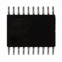
L6730C STMicroelectronics, L6730C Datasheet - Page 34

L6730C
Manufacturer Part Number
L6730C
Description
IC CTRLR ADJ STPDN SYNC 20-TSSOP
Manufacturer
STMicroelectronics
Type
Step-Down (Buck)r
Datasheet
1.L6730DTR.pdf
(50 pages)
Specifications of L6730C
Internal Switch(s)
No
Synchronous Rectifier
Yes
Number Of Outputs
1
Voltage - Output
Adj to 0.6V
Frequency - Switching
100kHz ~ 1MHz
Voltage - Input
1.8 ~ 14 V
Operating Temperature
-40°C ~ 85°C
Mounting Type
Surface Mount
Package / Case
20-TSSOP Exposed Pad, 20-eTSSOP, 20-HTSSOP
Package
HTSSOP20, QFN4x4 24L
For Use With
497-5868 - EVAL BOARD 30A 400KHZ L6730497-5501 - EVAL BOARD FOR L6730XX
Lead Free Status / RoHS Status
Lead free / RoHS Compliant
Current - Output
-
Power - Output
-
Application details
6.5
Figure 28. Efficiency in discontinuous-current-mode and continuous-current-mode.
34/50
0.7
0.6
0.5
0.4
0.3
0.2
0.1
Two quadrant or one quadrant operation mode (L6730C)
After the soft-start phase the L6730C can work in source only (one quadrant operation mode)
or in sink/source (two quadrant operation mode), depending on the setting of the multifunction
pin (see
related to the application. One quadrant operation mode permits to have a higher efficiency at
light load, because the converter works in discontinuous mode (see
in some cases, in order to maintain a constant switching frequency, it’s preferable to work in two
quadrants, even at light load. In this way the reduction of the switching frequency due to the
pulse skipping is avoided. To parallel two or more modules is requested the one quadrant
operation in order not to have current sinking between different converters. Finally the two
quadrant operation allows faster recovers after negative load transient. For example, let’s
consider that the load current falls down from I
than L/V
instantaneously setting to 0% the duty-cycle, the energy ½*L*I
transferred to the output capacitors, increasing the output voltage. If the converter can sink
current this overvoltage can be faster eliminated.
0
0.2
OUT
Chapter 5.10 on page
(where L is the inductor value). Even considering that the converter reacts
0.4
0.6
OUTP UT CURRENT (A)
EFFIC IENC Y: D C M vs. CC M
0.8
25). The choice of one or two quadrant operation mode is
1
1.2
1.4
OUT
1.6
to 0A with a slew rate sufficiently greater
1.8
OUT
2
2
stored in the inductor will be
Figure
E FFICIENCY DCM
E FFICIENCY CCM
L6730C - L6730D
28.). Nevertheless


