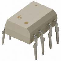
TLP525G-2(F) Toshiba, TLP525G-2(F) Datasheet - Page 40

TLP525G-2(F)
Manufacturer Part Number
TLP525G-2(F)
Description
PHOTOCOUPLER DUAL TRIAC OUT 8DIP
Manufacturer
Toshiba
Specifications of TLP525G-2(F)
Voltage - Isolation
2500Vrms
Number Of Channels
2
Voltage - Off State
400V
Output Type
AC, Triac, Standard
Current - Gate Trigger (igt) (max)
10mA
Current - Hold (ih)
200µA
Current - Dc Forward (if)
20mA
Current - Output / Channel
80mA
Mounting Type
Through Hole
Package / Case
8-DIP (0.300", 7.62mm)
Output Device
Triac
Isolation Voltage
2500 Vrms
Peak Output Voltage (vdrm)
400 V
Maximum Input Voltage
1.3 V
Maximum Output Voltage
400 V
Minimum Trigger Current
5 mA(Typ)
Configuration
2 Channel
Maximum Continuous Output Current
80 mA
Maximum Input Current
50 mA
Maximum Operating Temperature
+ 85 C
Maximum Reverse Diode Voltage
5 V
Minimum Operating Temperature
- 25 C
Mounting Style
Through Hole
Typical Input Voltage
1.15 V
Zero-crossing Circuit
No
Lead Free Status / RoHS Status
Lead free / RoHS Compliant
Other names
TLP525G-2F
Available stocks
Company
Part Number
Manufacturer
Quantity
Price
Part Number:
TLP525G-2(F)
Manufacturer:
TOSHIBA/东芝
Quantity:
20 000
4
Triac-Output Photocouplers
Note 2: BSI and IEC: : Approved (supplementary or basic insulation)
Some of the photocouplers with triac output are also manufactured by Toshiba Semiconductor Thailand Co.,Ltd. For detailed information, please contact your nearest Toshiba sales
representative.
TLP360J
TLP360JF
TLP361J
TLP361JF
TLP363J
TLP363JF
TP560G
TP560J
TP561G
TP561J
TLP3022 ( S )
TLP3022F ( S )
TLP3023 ( S )
TLP3023F ( S )
TLP3052 ( S )
TLP3052F ( S )
TLP3042 ( S )
TLP3043 ( S )
TLP3062 ( S )
TLP3062F ( S )
TLP3063 ( S )
TLP3063F ( S )
TLP3064 ( S )
TLP3082 ( S )
TLP3782 ( S )
TLP3782F ( S )
TLP3783 ( S )
TLP3783F ( S )
Part Number
TÜV and VDE: : Approved
For the latest information, please contact your nearest Toshiba sales representative.
Selection Guide
EN 60065- and IEC 60065-approved, EN 60950- and IEC 60950-approved
EN 60747-5-2-approved with option V4 or D4
Pin Configuration
6
1
6
1
6
1
6
1
4
1
4
1
2
2
2
2
ZC
3
2
3
2
ZC
: Design which meets safety standard/approval pending as of January 2011
4
3
4
3
4
3
ZC
4
3
DIP4
Non-zero cross
DIP4
Zero cross
DIP4
Zero cross
High impulse noise
immunity
V
DIP6
General-purpose
Non-zero cross
DIP6
General-purpose
Zero cross
DIP6
SEMKO-approved
Non-zero cross
DIP6
High V
SEMKO-approved
Non-zero cross
DIP6
SEMKO-approved
Zero cross
DIP6
SEMKO-approved
High V
Zero cross
DIP6
SEMKO-approved
Zero cross
DIP6
Zero cross
DIP6
High impulse noise
immunity
V
N
N
= 2000 V (typ.)
= 1500 V (typ.)
Features
DRM
DRM
Tingger LED Current,
Rank
: Approved (reinforced insulation)
IFT7
IFT7
IFT7
IFT5
IFT7
IFT7
IFT5
IFT7
–
–
–
–
–
–
–
–
–
–
–
–
–
–
–
–
–
–
I
FT
10 mA
10 mA
10 mA
10 mA
10 mA
10 mA
10 mA
10 mA
10 mA
10 mA
10 mA
10 mA
10 mA
7 mA
7 mA
7 mA
5 mA
7 mA
7 mA
5 mA
7 mA
5 mA
5 mA
5 mA
3 mA
5 mA
Max
40
3.0 V
3.0 V
3.0 V
3.0 V
3.0 V
3.0 V
Max
Peak On-State
Voltage, V
100 mA
100 mA
100 mA
100 mA
100 mA
100 mA
@I
: Design which meets safety standard/approval pending as of January 2011
TM
TM
Off-State
Terminal
Voltage
Output
600 V
600 V
400 V
600 V
400 V
600 V
400 V
600 V
400 V
600 V
600 V
600 V
V
DRM
@1 Minute
Vrms
Vrms
Vrms
Vrms
5000
2500
5000
5000
BVs
UL
c-UL
Safety Standards
TÜV
VDE
(2)
BSI
IEC


