KP-FSD3 Panduit Corp, KP-FSD3 Datasheet - Page 458
KP-FSD3
Manufacturer Part Number
KP-FSD3
Description
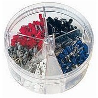
KIT FERRULE INS DIN AWG12-6
Manufacturer
Panduit Corp
Series
Pan-Term®r
Type
Ferrule Kitr
Datasheet
1.KP-FSD1.pdf
(1040 pages)
Specifications of KP-FSD3
Kit Type
Ferrule - Wire End
Values
100 pcs - Assorted Insulated 12 ~ 6 AWG Ferrules
Kit Contents
50 Pieces Of FSD81-10, 20 Pieces Each Of FSD82-12 And FSD83-12, 10 Pieces Of FSD84-12
Mounting Method
Crimp
Where Used
To terminate stranded wire for insertion into terminal blocks
Lead Free Status / Rohs Status
Lead free / RoHS Compliant


Management
Identification
Accessories
Connectors
Connectors
& Write-On
Protection
Grounding
Pre-Printed
Cable Ties
Terminals
Permanent
Solutions
Overview
Steel Ties
Lockout/
& Safety
Stainless
Raceway
Abrasion
Labeling
Systems
Markers
Tagout
System
Surface
Wiring
Power
Labels
Index
Cable
Cable
Duct
C3.44
E5.
B1.
B2.
B3.
C1.
C2.
C3.
C4.
D1.
D2.
D3.
E1.
E2.
E3.
E4.
A.
F.
Dry-Shrink
Technical Data
Product Type
Order number of pieces required, in multiples of Standard Package Quantity.
HSTTPN
HSTTRA
HSTTVA
HSTT4A
HSTTV
HSTTP
HSTTN
HSTTT
HSTTK
HSTTA
HSTT
HST
and cable markers and continuous inspection of splices.
Black is U.V. Resistant. Suitable for use in dry locations.
Crystal clear product that is excellent for protecting wire
Use where UL recognition with VW-1 rating is required.
higher shrink temperatures, reduces application time to
in appliance handles and bus bars. Good cut through
insulate, protect, identify, etc. Black is U.V. Resistant.
and corrosion. The 4:1 shrink ratio is a benefit when
Can be used with fiber optics and as a strain relief
working with large transitions. Use where a flexible
and solder-iron resistance. Black is U.V. Resistant.
when working with connector to cable transitions.
™
Ripple free conformance around sharp bends as
High temperature, strain relief, resists corrosive
Use where the wire component cannot tolerate
Seals and protects components from moisture
Economical and easy way to insulate, protect,
components forming a rugged and heavy duty
and splices above or below ground, 3:1 shrink
tubing is needed. Suitable for damp locations.
tubing is needed. Suitable for damp locations.
components in a wide variety of applications.
Insulation and abrasion resistance, extensive
atmosphere, self lubrication and non-wetting.
harness and identify electrical and electronic
moisture and corrosion. Use where a flexible
,
components. The 3:1 shrink ratio is a benefit
rich environment. Insulation of heater leads.
ratio. Suitable for outdoor and wet locations.
connectors in a high temperature or solvent
Excellent chemical resistance especially to
for high density connectors. U.V. Resistant.
covering. The 2.5:1 shrink ratio is a benefit
military uses on vehicles and ship-board.
Seals and protects electrical connections
High insulation and abrasion resistance.
transitions. Suitable for damp locations.
Damp-Shrink
Protection and strain relief for wires or
when working with connector to cable
fuels and oils. Black is U.V. Resistant.
Seals and protects components from
Environmentally seals and protects
Environmentally seals and protects
Suitable for use in dry locations.
Suitable for use in dry locations.
Suitable for use in dry locations.
Suitable for use in dry locations.
Suitable for use in dry locations.
Suitable for use in dry locations.
Suitable for damp locations.
Typical Applications
™
General Information
, and
ELECTRICAL SOLUTIONS
Wet-Shrink
Specific Gravity
Class 1, 1.35
ASTM D792
ASTM D792
Class 2, 1.0
1.35 MAX.
2.2 MAX.
1.8 MAX.
1.2 MAX.
ASTM
ASTM
ASTM
D792
D792
D792
1.50
1.30
N/A
N/A
N/A
N/A
N/A
™
Heat Shrink Tubing
Self Extinguishing
Self Extinguishing
VW-1 per UL 224
VW-1 per UL 224
VW-1 per UL 224
VW-1 per UL 224
VW-1 per UL 224
VW-1 per UL 224
VW-1 per UL 224
Flammability
Extinguishing
ASTM D2671
Extinguishing
ASTM D2671
ASTM D2671
Procedure B
Procedure B
Procedure B
Class 1 Self
ASTM D876
Self
N/A
Water Absorption Dielectric Strength
1.0% MAX.
1.0% MAX.
1.0% MAX.
.01% MAX.
1.0% MAX.
1.0% MAX.
.5% MAX.
.5% MAX.
.5% MAX.
.5% MAX.
.5% MAX.
.5% MAX.
ASTM
ASTM
ASTM
ASTM
ASTM
ASTM
ASTM
ASTM
ASTM
ASTM
ASTM
ASTM
D570
D570
D570
D570
D570
D570
D570
D570
D570
D570
D570
D570
(19.7 Kv/mm) min.
(19.7 Kv/mm) min.
(15.8 Kv/mm) min.
(15.8 Kv/mm) min.
(11.8 Kv/mm) min.
(31.5 Kv/mm) min.
(19.7 Kv/mm) min.
(11.8 Kv/mm) min.
(19.7 Kv/mm) min.
(19.7 Kv/mm) min.
(31.5 Kv/mm) min
(23.6 Kv/mm) min
Size to (12.7mm)
(7.9 Kv/mm) min.
Over (12.7mm)
ASTM D2671
ASTM D2671
ASTM D2671
ASTM D2671
ASTM D2671
ASTM D2671
ASTM D2671
ASTM D2671
ASTM D2671
ASTM D2671
ASTM D2671
ASTM D2671
500 V/MIL.
500 V/MIL.
400 V/MIL.
400 V/MIL.
300 V/MIL.
800 V/MIL.
800 V/MIL.
600 V/MIL.
500 V/MIL.
300 V/MIL.
500 V/MIL.
500 V/MIL.
200 V/MIL.