KP-FSD3 Panduit Corp, KP-FSD3 Datasheet - Page 57
KP-FSD3
Manufacturer Part Number
KP-FSD3
Description
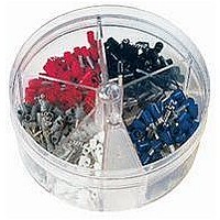
KIT FERRULE INS DIN AWG12-6
Manufacturer
Panduit Corp
Series
Pan-Term®r
Type
Ferrule Kitr
Datasheet
1.KP-FSD1.pdf
(1040 pages)
Specifications of KP-FSD3
Kit Type
Ferrule - Wire End
Values
100 pcs - Assorted Insulated 12 ~ 6 AWG Ferrules
Kit Contents
50 Pieces Of FSD81-10, 20 Pieces Each Of FSD82-12 And FSD83-12, 10 Pieces Of FSD84-12
Mounting Method
Crimp
Where Used
To terminate stranded wire for insertion into terminal blocks
Lead Free Status / Rohs Status
Lead free / RoHS Compliant


• Weather resistant material has greater resistance to damage
• Heat stabilized material for high temperature applications
• Used to secure a cable bundle to another surface such as a
Weather Resistant Nylon 6.6
Miniature Cross Section
Intermediate Cross Section
Standard Cross Section
Light-Heavy Cross Section
Heat Stabilized Nylon 6.6
Miniature Cross Section
Intermediate Cross Section
Standard Cross Section
Light-Heavy Cross Section
Note: UL Recognized and CSA Certified except PLC2H/4H in Weather Resistant material (0).
Part Number
PLC1M-S4-C0
PLC1.5I-S8-C0
PLC2S-S6-C0
PLC2S-S10-C0
PLC3S-S10-C0
PLC4S-S10-C0
PLC2H-S25-TL0
PLC4H-S25-L0
PLC1M-S4-M30
PLC1.5I-S8-M30
PLC2S-S10-M30
PLC4S-S10-M30
PLC2H-S25-TL30
PLC4H-S25-TL30
caused by ultraviolet light – indoor or outdoor use
up to 239°F (115°C) – indoor use
control panel, communication rack, wall or ceiling
Pan-Ty
12.0 305 .190 4.8 .052
15.0 381 .190 4.8 .052
15.1 384 .300 7.6 .075
15.0 381 .190 4.8 .052
15.1 384 .300 7.6 .075
4.3
6.1
7.9
7.9
9.0
4.3
6.1
7.9
9.0
In.
Length
mm
109 .100 2.5 .045
155 .135 3.4 .045
201 .190 4.8 .047
201 .190 4.8 .047
229 .300 7.6 .075
109 .100 2.5 .045
155 .135 3.4 .045
201 .190 4.8 .047
229 .300 7.6 .075
®
Clamp Ties – Weather Resistant and Heat Stabilized Nylon 6.6
In.
Width
mm
For technical assistance in the U.S., call 866-405-6654 (outside the U.S., see inside back cover for directory)
Thickness
In.
mm
1.1
1.1
1.2
1.2
1.3
1.3
1.9
1.9
1.1
1.1
1.2
1.3
1.9
1.9
ELECTRICAL SOLUTIONS
.122 3.1
.174 4.4
.148 3.8
.200 5.1
.200 5.1
.200 5.1
.260 6.6
.260 6.6
.122 3.1
.174 4.4
.200 5.1
.200 5.1
.260 6.6
.260 6.6
Nominal
In.
Hole
Dia.
mm
Screw
Size
#10
#10
#10
#10
#10
1/4
1/4
1/4
1/4
• Design allows for bundling before or after screwing clamp in place
• One-piece construction for consistent performance and reliability
• Curved tip is easy to pick up from flat surfaces and allows faster
#4
#8
#6
#4
#8
initial threading to speed installation
Metric
Screw
M2.5
M2.5
Size
M4
M3
M5
M5
M5
M6
M6
M4
M5
M5
M6
M6
1.25
1.84
1.84
3.00
4.00 102
2.00
4.00 102 120
1.25
1.84
4.00 102
2.00
4.00 102 120
.75
.75
In.
Bundle
Max.
Dia.
mm Lbs.
19
32
47
47
76
51
19
32
47
51
Tensile Str.
120
120
18
40
50
50
50
50
18
40
50
50
Loop
Min.
178
222
222
222
222
534
534
178
222
222
534
534
80
80
N
Recommended
STH2, ST3EH
STH2, ST3EH
GS4EH, PTH,
GS4EH, PTH,
PPTS, STS2
PPTS, STS2
STS2, STH2
GTH, GS4H,
PPTS, STS2
PPTS, STS2
STS2, STH2
GTH, GS4H,
GTS, GTSL,
GTS, GTSL,
GTS, GTSL,
GS2B, GTH,
GS4H, PTS,
GTS, GTSL,
GTS, GTSL,
GTS, GTSL,
GS2B, GTH,
GS4H, PTS,
GS2B, PTS,
GS2B, PTS,
PTH, PPTS,
GS2B, PTS,
GS2B, PTS,
PTH, PPTS,
Installation
Tool
Pkg.
1000 50000
1000 25000
1000 10000
1000
Std.
Qty.
100
100
100
100
100
100
250
250
250
50
1000
1000
1000
1000
1000
1000
2500
5000
2500
2500
Std.
Ctn.
Qty.
500
B1.27
Management
Identification
Accessories
Connectors
Connectors
Grounding
Pre-Printed
& Write-On
Protection
Permanent
Solutions
Cable Ties
Terminals
Lockout/
Overview
Steel Ties
& Safety
Stainless
Raceway
Abrasion
Labeling
Systems
Surface
Markers
Tagout
System
Wiring
Labels
Power
Cable
Cable
Index
Duct
E5.
B1.
B2.
B3.
D1.
D2.
D3.
C1.
C2.
C3.
C4.
E1.
E2.
E3.
E4.
A.
F.