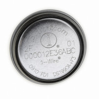
DS1990A-F3+ Maxim Integrated Products, DS1990A-F3+ Datasheet - Page 2

DS1990A-F3+
Manufacturer Part Number
DS1990A-F3+
Description
IC IBUTTON SERIAL NUMBER F3
Manufacturer
Maxim Integrated Products
Series
iButton®r
Type
Serial Number IButtonr
Datasheet
1.DS1990A-F5.pdf
(10 pages)
Specifications of DS1990A-F3+
Rohs Information
IButton RoHS Compliance Plan
Memory Size
8B
Memory Type
ROM
Maximum Operating Temperature
+ 85 C
Package / Case
F3 MicroCan
Minimum Operating Temperature
- 40 C
Mounting Style
SMD/SMT
Ic Function
Serial Number IButton IC
Supply Voltage Range
2.8V To 6V
Operating Temperature Range
-40°C To +85°C
Digital Ic Case Style
F3 IButton
Termination Type
SMD
Supply Voltage Min
2.8V
Rohs Compliant
Yes
Filter Terminals
SMD
Lead Free Status / RoHS Status
Lead free / RoHS Compliant
Serial Number iButton
ABSOLUTE MAXIMUM RATINGS
IO Voltage Range to GND .....................................-0.5V to +6.0V
IO Sink Current....................................................................20mA
ELECTRICAL CHARACTERISTICS
(T
Stresses beyond those listed under “Absolute Maximum Ratings” may cause permanent damage to the device. These are stress ratings only, and functional
operation of the device at these or any other conditions beyond those indicated in the operational sections of the specifications is not implied. Exposure to
absolute maximum rating conditions for extended periods may affect device reliability.
Note 1:
Note 2:
Note 3:
Note 4:
Note 5:
Note 6:
Note 7:
2
IO PIN: GENERAL DATA
1-Wire Pullup Voltage
1-Wire Pullup Resistance
Input Capacitance
Input Load Current
Input Low Voltage
Input High Voltage
Output Low Voltage at 4mA
Operating Charge
Recovery Time
Time Slot Duration
IO PIN: 1-Wire RESET, PRESENCE-DETECT CYCLE
Reset Low Time
Reset High Time
Presence-Detect High Time
Presence-Detect Low Time
Presence-Detect Sample Time
IO PIN: 1-Wire WRITE
Write-Zero Low Time
Write-One Low Time
IO PIN: 1-Wire READ
Read Low Time
Read Sample Time
A
= -40°C to +85°C.)
_______________________________________________________________________________________
All voltages are referenced to ground.
External pullup voltage. See Figure 4.
System requirement.
Full R
fixed R
Wire recovery times. The specified value here applies to systems with only one device and with the minimum 1-Wire recov-
ery times. For more heavily loaded systems, an active pullup such as that found in the DS2480B may be required.
Capacitance on the IO pin could be 800pF when power is first applied. If a 5kΩ resistor is used to pull up the IO line to
V
Guaranteed by design, simulation only. Not production tested.
Input load is to ground.
PARAMETER
PUP
, 5µs after power has been applied the parasite capacitance will not affect normal communications.
PUP
PUP
range is guaranteed by design and simulation and not production tested. Production testing performed at a
value. Maximum allowable pullup resistance is a function of the number of 1-Wire devices in the system and 1-
SYMBOL
t
t
V
R
t
t
t
t
t
t
t
Q
SLOT
RSTH
t
V
RSTL
C
MSR
V
REC
PDH
MSP
W0L
W1L
V
PDL
t
PUP
PUP
RL
I
OL
OP
IH
IO
L
IL
(Notes 1, 2)
(Notes 3, 4)
(Notes 5, 6)
(Note 7)
(Notes 1, 3, 8)
(Notes 1, 9)
(Note 1)
(Notes 6, 10)
(Note 3)
(Note 3)
(Notes 3, 11)
(Notes 3, 12)
(Note 13)
(Note 3)
(Notes 3, 14)
(Notes 3, 14)
(Notes 3, 15)
(Notes 3, 15)
CONDITIONS
Junction Temperature ......................................................+125°C
Storage Temperature Range .............................-55°C to +125°C
t
RL
MIN
480
480
2.8
0.6
2.2
61
15
60
60
60
1
1
1
+
TYP
0.25
100
30
15 -
MAX
800
240
120
6.0
0.3
0.4
60
75
15
15
5
UNITS
k
nC
pF
μA
μs
μs
μs
μs
μs
μs
μs
μs
μs
μs
μs
V
V
V
V


