MT18HTF25672AY-667A3 Micron Technology Inc, MT18HTF25672AY-667A3 Datasheet - Page 11
MT18HTF25672AY-667A3
Manufacturer Part Number
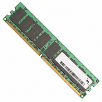
MT18HTF25672AY-667A3
Description
MODULE DDR2 2GB 240-DIMM
Manufacturer
Micron Technology Inc
Specifications of MT18HTF25672AY-667A3
Memory Type
DDR2 SDRAM
Memory Size
2GB
Speed
667MT/s
Package / Case
240-DIMM
Main Category
DRAM Module
Sub-category
DDR2 SDRAM
Module Type
240UDIMM
Device Core Size
72b
Organization
256Mx72
Total Density
2GByte
Chip Density
1Gb
Access Time (max)
45ps
Maximum Clock Rate
667MHz
Operating Supply Voltage (typ)
1.8V
Operating Current
1.503A
Number Of Elements
18
Operating Supply Voltage (max)
1.9V
Operating Supply Voltage (min)
1.7V
Operating Temp Range
0C to 85C
Operating Temperature Classification
Commercial
Pin Count
240
Mounting
Socket
Lead Free Status / RoHS Status
Lead free / RoHS Compliant


Table 13:
PDF: 09005aef80e8ad4d/Source: 09005aef80e785e6
HTF18C64_128_256_512x72A.fm - Rev. H 5/08 EN
Parameter/Condition
Operating one bank active-precharge current:
t
valid commands; Address bus inputs are switching; Data bus inputs are
switching
Operating one bank active-read-precharge current: I
BL = 4, CL = CL (I
t
valid commands; Address bus inputs are switching; Data pattern is same
as I
Precharge power-down current: All device banks idle;
CKE is LOW; Other control and address bus inputs are stable; Data bus
inputs are floating
Precharge quiet standby current: All device banks idle;
CKE is HIGH, S# is HIGH; Other control and address bus inputs are stable;
Data bus inputs are floating
Precharge standby current: All device banks idle;
HIGH, S# is HIGH; Other control and address bus inputs are switching;
Data bus inputs are switching
Active power-down current: All device banks open;
t
inputs are stable; Data bus inputs are floating
Active standby current: All device banks open;
t
valid commands; Other control and address bus inputs are switching; Data
bus inputs are switching
Operating burst write current: All device banks open; Continuous
burst writes; BL = 4, CL = CL (I
(I
Address bus inputs are switching; Data bus inputs are switching
Operating burst read current: All device banks open; Continuous burst
reads; I
t
valid commands; Address bus inputs are switching; Data bus inputs are
switching
Burst refresh current:
t
Other control and address bus inputs are switching; Data bus inputs are
switching
Self refresh current: CK and CK# at 0V; CKE ≤ 0.2V; Other control and
address bus inputs are floating; Data bus inputs are floating
Operating bank interleave read current: All device banks interleaving
reads; I
=
HIGH, S# is HIGH between valid commands; Address bus inputs are stable
during DESELECTs; Data bus inputs are switching
RC =
RAS =
CK =
RAS =
RAS =
RFC (I
DD
t
CK (I
DD
),
t
4W
t
t
DD
RC (I
CK (I
RP =
t
t
t
OUT
OUT
DD
RAS MIN (I
RAS MAX (I
RAS MAX (I
) interval; CKE is HIGH, S# is HIGH between valid commands;
),
DD
DD
= 0mA; BL = 4, CL = CL (I
= 0mA; BL = 4, CL = CL (I
t
t
RP (I
RC =
),
); CKE is LOW; Other control and address bus
DDR2 I
Values shown for MT47H128M8 DDR2 SDRAM only and are computed from values specified in the
1Gb (128 Meg x 8) component data sheet
t
RAS =
DD
DD
t
RC (I
DD
Notes:
), AL = 0;
); CKE is HIGH, S# is HIGH between valid commands;
DD
DD
),
),
),
DD
t
t
DD
RAS MIN (I
RCD =
t
t
RP =
RP =
t
CK =
),
Specifications and Conditions (Die Revision A) – 2GB
t
RRD =
1. Value calculated as one module rank in this operating condition and all other module ranks
2. Value calculated reflects all module ranks in this operating condition.
t
512MB, 1GB, 2GB, 4GB (x72, DR, ECC) 240-Pin DDR2 SDRAM UDIMM
CK =
DD
t
t
t
RP (I
RP (I
t
RCD (I
CK (I
in I
), AL = 0;
DD
DD
t
t
DD
DD
CK (I
RRD (I
DD
DD
DD
); CKE is HIGH, S# is HIGH between
DD
2P (CKE LOW).
); CKE is HIGH, S# is HIGH between
); CKE is HIGH, S# is HIGH between
), AL =
), AL = 0;
); REFRESH command at every
); CKE is HIGH, S# is HIGH between
DD
t
DD
CK =
),
),
t
RC =
t
RCD (I
t
RCD =
t
CK (I
t
CK =
t
t
RC (I
CK =
t
DD
DD
t
CK =
CK =
t
t
RCD (I
CK (I
) - 1 ×
),
DD
t
t
CK (I
RAS =
t
),
t
OUT
t
CK (I
CK =
t
CK (I
DD
CK =
Fast PDN exit
MR[12] = 0
Slow PDN exit
MR[12] = 1
DD
11
t
DD
CK (I
),
= 0mA;
); CKE is
DD
DD
t
t
),
RAS MAX
CK (I
t
CK (I
),
); CKE is
DD
);
DD
DD
Micron Technology, Inc., reserves the right to change products or specifications without notice.
t
CK
);
);
Symbol
I
I
I
I
I
I
I
DD
DD
DD
DD
I
I
DD
DD
DD
I
I
I
DD
DD
DD
DD
DD
4W
2Q
2N
3N
4R
2P
3P
0
1
5
6
7
1
1
2
2
1
2
2
2
2
1
2
1
1,053
1,170
1,260 1,080
1,350 1,260
1,728 1,503 1,233 1,053
1,773 1,503 1,368 1,053
5,040 4,680 4,500 3,960
3,078 2,763 2,673 2,403
-80E/
-800
963
126
810
252
126
Electrical Specifications
-667
873
963
126
990
720
252
126
©2003 Micron Technology, Inc. All rights reserved.
-53E
783
918
126
738
810
630
252
990
126
-40E
693
783
126
630
720
630
252
810
126
Units
mA
mA
mA
mA
mA
mA
mA
mA
mA
mA
mA
mA
mA
Related parts for MT18HTF25672AY-667A3
Image
Part Number
Description
Manufacturer
Datasheet
Request
R

Part Number:
Description:
IC SDRAM 64MBIT 133MHZ 54TSOP
Manufacturer:
Micron Technology Inc
Datasheet:

Part Number:
Description:
IC SDRAM 64MBIT 5.5NS 86TSOP
Manufacturer:
Micron Technology Inc
Datasheet:
Part Number:
Description:
IC SDRAM 64MBIT 200MHZ 86TSOP
Manufacturer:
Micron Technology Inc
Datasheet:
Part Number:
Description:
IC SDRAM 64MBIT 133MHZ 54TSOP
Manufacturer:
Micron Technology Inc
Datasheet:
Part Number:
Description:
IC SDRAM 128MBIT 133MHZ 54TSOP
Manufacturer:
Micron Technology Inc
Datasheet:

Part Number:
Description:
IC SDRAM 256MBIT 133MHZ 90VFBGA
Manufacturer:
Micron Technology Inc
Datasheet:
Part Number:
Description:
IC SDRAM 128MBIT 133MHZ 54TSOP
Manufacturer:
Micron Technology Inc
Datasheet:
Part Number:
Description:
IC SDRAM 256MBIT 133MHZ 54TSOP
Manufacturer:
Micron Technology Inc
Datasheet:

Part Number:
Description:
IC DDR SDRAM 512MBIT 6NS 66TSOP
Manufacturer:
Micron Technology Inc
Datasheet:
Part Number:
Description:
IC SDRAM 128MBIT 167MHZ 86TSOP
Manufacturer:
Micron Technology Inc
Datasheet:
Part Number:
Description:
IC SDRAM 128MBIT 143MHZ 86TSOP
Manufacturer:
Micron Technology Inc
Datasheet:

Part Number:
Description:
SDRAM 256M-BIT 1.8V 54-PIN VFBGA
Manufacturer:
Micron Technology Inc
Datasheet:
Part Number:
Description:
IC SDRAM 128MBIT 143MHZ 86TSOP
Manufacturer:
Micron Technology Inc
Datasheet:

Part Number:
Description:
IC SDRAM 128MBIT 125MHZ 54VFBGA
Manufacturer:
Micron Technology Inc
Datasheet:
Part Number:
Description:
IC SDRAM 128MBIT 125MHZ 54VFBGA
Manufacturer:
Micron Technology Inc
Datasheet: