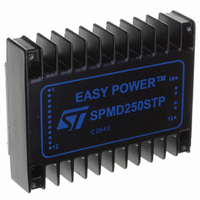
SPMD250STP STMicroelectronics, SPMD250STP Datasheet - Page 16

SPMD250STP
Manufacturer Part Number
SPMD250STP
Description
MOD STEPPER MOTOR DRV 2.5A BIPO
Manufacturer
STMicroelectronics
Series
EASY POWER™r
Type
Stepper Motor Driverr
Datasheet
1.SPMD250STP.pdf
(28 pages)
Specifications of SPMD250STP
Motor Type
Stepper, Bipolar
Number Of Motors
1
Voltage - Output
40V
Voltage - Logic Supply
4.5 V ~ 5.5 V
Current - Output
2.5A
Transistor Type
MOSFET
Termination Style
PC Pin
Operating Temperature Classification
Industrial
Operating Supply Voltage (min)
12V
Operating Supply Voltage (typ)
5V
Operating Supply Voltage (max)
40V
Product
Stepper Motor Controllers / Drivers
Operating Supply Voltage
5 V
Mounting Style
SMD/SMT
For Use With
497-10050 - BOARD EVAL SPMD250497-9011 - DEMO SYSTEM BASED ON SPMD250STP
Lead Free Status / RoHS Status
Lead free / RoHS Compliant
Other names
497-8416
Available stocks
Company
Part Number
Manufacturer
Quantity
Price
Company:
Part Number:
SPMD250STP
Manufacturer:
AD
Quantity:
101
Company:
Part Number:
SPMD250STP
Manufacturer:
STMicroelectronics
Quantity:
136
User notes
9
9.1
9.2
9.3
9.4
16/28
User notes
Supply voltage
The recommended operating maximum supply voltage must include the ripple voltage for
the Vs rail, and a 5 V ± 5% for the Vss line is required.
The two supply voltages must to be correctly sequenced to avoid any possible erroneous
positioning of the power stages. The correct power-up and power-down sequences are:
●
●
Case grounding
The module case is electrically floating. To have a right case grounding, connect module pin
13 (GND2) to the nearest case fixing pin (see
additional effective EMI shield, the PCB area below the module can be used as an effective
sixth side shield.
Thermal characteristics
The case-to-ambient thermal resistance is 5 °C/W. This produces a 50 °C temperature
increase of the module surface for 10 W of internal dissipation.
According to ambient temperature and/or to power dissipation, an additional heatsink or
forced ventilation may be required. (See derating curves
Supply line impedance
The module has an internal capacitor connected across the supply pins (18 and 13) to
assure the circuit stability. This capacitor cannot handle high values of current ripple, and
would be permanently damaged if the primary energy source impedance is not adequate.
The use of a low ESR, high ripple current 470 µF capacitor located as close to the module
as possible is recommended.
When space is a limitation, a 22 µF ceramic multi-layer capacitor connected across the
module input pins must be used.
Power-up
1.Vss (5 V) is applied with enable = Low
2. Vs (the motor supply voltage) is applied
3. Enable is brought high
Power-down
1.Enable is brought low
2. Vs is switched off
3. Vss is switched off.
Doc ID 14350 Rev 2
Figure
4,
Figure 19
Figure
16).
and
Figure
SPMD250STP
20). To obtain


