SPMD150STP STMicroelectronics, SPMD150STP Datasheet
SPMD150STP
Specifications of SPMD150STP
Available stocks


Related parts for SPMD150STP


SPMD150STP Summary of contents
Page 1
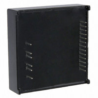
... Module size: 50.8 x 50.8 x 14.7 mm ■ Operating temperature range -40° °C Description The SPMD150STP is a highly integrated stepper motor driver module, that allows the user to easily design a complete motor control system for two- phase bipolar stepper motors, interfacing directly the microprocessor to the motor. ...
Page 2
... Stepping sequence generation . . . . . . . . . . . . . . . . . . . . . . . . . . . . . . . . . 16 4.5.1 4.5.2 4.5.3 4.5.4 4.6 Non-dissipative overcurrent protection . . . . . . . . . . . . . . . . . . . . . . . . . . . 19 4.7 Thermal characteristics . . . . . . . . . . . . . . . . . . . . . . . . . . . . . . . . . . . . . . 20 4.8 Case grounding . . . . . . . . . . . . . . . . . . . . . . . . . . . . . . . . . . . . . . . . . . . . 20 5 Package mechanical data . . . . . . . . . . . . . . . . . . . . . . . . . . . . . . . . . . . . 21 6 Revision history . . . . . . . . . . . . . . . . . . . . . . . . . . . . . . . . . . . . . . . . . . . 22 2/23 Half step mode . . . . . . . . . . . . . . . . . . . . . . . . . . . . . . . . . . . . . . . . . . . . 16 Normal drive mode (full-step two-phase-on Wave drive mode (Full-step one-phase-on Microstepping . . . . . . . . . . . . . . . . . . . . . . . . . . . . . . . . . . . . . . . . . . . . 18 Doc ID 17160 Rev 1 SPMD150STP ...
Page 3
... SPMD150STP 1 Block diagram and pin connection Figure 1. Block diagram Figure 2. Connection diagram (top view) Block diagram and pin connection Doc ID 17160 Rev 1 3/23 ...
Page 4
... Connect this pin to a properly scaled REF (Pin2) voltage, to fix the maximum phase output current. Connecting a variable voltage source (i.e. microcontroller DAC possible to perform micro-stepping drive. The pin is internally connected to a 100kΩ pull-down resistor, with a 470pF parallel capacitor. Doc ID 17160 Rev 1 SPMD150STP Function ...
Page 5
... SPMD150STP Table 2. Pin description (continued) Pin N. Name 12 RCB 13 GND1 14 GND2 15 PHD 16 PHC 17 PHB 18 PHA 19 VS Phase C/D current controller -Time set pin. Use this pin to set the desired Off-time of the switching current controller. A 470pF capacitor and 56kΩ resistor are internally connected between this pin and GND1 (Pin13), giving a 16 µ ...
Page 6
... DC logic supply voltage (pin1) SS Voltage range at pins VREFA, VREFB, RCA, RCB, EN, V input CLOCK, CW/CCW, HALF/FULL, CONTROL Io-pk Output peak current T Storage temperature range stg T Operating case temperature range op 6/23 Parameter Doc ID 17160 Rev 1 SPMD150STP Value Unit -0 2.5 A – +105 °C – +85 °C ...
Page 7
... SPMD150STP 3 Electrical characteristics °C and V A Table 4. Electrical characteristics Symbol Parameter Power stage V DC supply voltage S I Quiescent supply current (pin19 Turn-on Input threshold Sth(ON) V Turn-off Input threshold Sth(OFF) Output voltage drop (VS to pins ΔV VS-PH 15,16,17,18) Output voltage drop (Pins15,16,17,18 to Δ ...
Page 8
... Io=2.5A, resistive load (Figure 3) Io=2.5A, resistive load (Figure 3) Io=2.5A, resistive load (Figure 4) (Figure 5) (Figure 5) (Figure 6) (Figure 6) (Figure 6) (Figure 6) Doc ID 17160 Rev 1 SPMD150STP Value Unit Min Typ Max 10 uA 1.21 1.225 1. kΩ 100 kΩ 100 250 400 ns 300 550 800 ns 40 ...
Page 9
... SPMD150STP Figure 3. Switching characteristic definition Figure 4. Clock to output delay time Figure 5. Minimum timing definition: clock Doc ID 17160 Rev 1 Electrical characteristics 9/23 ...
Page 10
... Electrical characteristics Figure 6. Minimum timing definition: logic inputs Figure 7. Overcurrent detection timing definition 10/23 Doc ID 17160 Rev 1 SPMD150STP ...
Page 11
... SPMD150STP 4 Function description and application information SPMD150STP can be seen divided in several main blocks (see ● Power stage, to drive the motor windings ● Logic interface, to interface the external signals to the internal circuitry ● PWM current controller, to fix and control the current flowing in the motor phase windings ● ...
Page 12
... RCA/B and GND1 inside the 12/23 Figure 11, toff versus Roff and Coff), the motor phase current re- Figure 10 Figure 10 Doc ID 17160 Rev 1 SPMD150STP DT (1µs). To set the toff DT and Figure 11; To set the toff ...
Page 13
... SPMD150STP module, fixing a typical 16 µs off time for both bridges. The toff value can be modified adding a capacitor to GND1, increasing the off time, or adding a resistor to GND1 decreasing the Off-time. Figure 10. toff setting circuit Roff = Ra // 56kΩ [kΩ], Coff = Ca + 470pF [pF] Figure 11. toff versus Roff and Coff To set the maximum motor phase current it is necessary to give the proper reference voltage at input VREFA (pin6) and VREFB (pin11) ...
Page 14
... In this case a proper resistor Rx must be connected between REF and GND1, VREFA and VREFB will be connected together to REF pin (see Use following equation to calculate Rx (500 x I 14/23 Figure 13), driving VREFA and VREFB pins together [319 - ( [kΩ] OUTx OUTx Doc ID 17160 Rev 1 SPMD150STP Figure 14), which supplies Figure 14). where I = [A] OUTx ...
Page 15
... SPMD150STP Figure 14. VREFx from internal source 4.4 Decay modes The CONTROL input is used to select the behavior of the bridge during the off time. When the CONTROL pin is low, the fast decay mode is selected and both transistors in the bridge are switched off during the off time. ...
Page 16
... RESET the phase sequencer is at state 1, home state. After each clock pulse the state changes following the sequence 1,2,3,4,5,6,7,8,… if CW/ CCW is high (Clockwise movement) or 1,8,7,6,5,4,3,2,… if CW/CCW is low (Counterclockwise movement). 16/23 Doc ID 17160 Rev 1 SPMD150STP Figure 17 shows the ...
Page 17
... SPMD150STP Figure 17. Half step mode 4.5.2 Normal drive mode (full-step two-phase-on) A Low level on the HALF/FULL input selects the full step mode. If the low level is applied when the state ma1chine ODD numbered state, the normal drive mode is selected. Figure 18 shows the motor current waveform state diagram for the state machine of the phase sequencer generator ...
Page 18
... VREFB are incremented or decremented through a defined number of level, this number gives the name to the micro-stepping granularity; as example micro-step per step means that, for each “standard” step there are 64 step values on VREFA/B (from zero to VREFA/B max and from VREFB/A max to zero, see Figure 20) 18/23 Doc ID 17160 Rev 1 SPMD150STP ...
Page 19
... SPMD150STP Figure 20. Microstepping 4.6 Non-dissipative overcurrent protection The SPMD150STP integrates an overcurrent protection circuit. This circuit provides protection against a short circuit to ground or between two phases of the bridge. To implement the over current detection, a sensing element that delivers a small but precise fraction of the output current is implemented with each high side power MOSFET. ...
Page 20
... Case grounding The module case is internally connected to GND1 (pin13) and GND2 (pin14). To obtain additional effective EMI shield, the PCB area below the module can be used as an effective sixth side shield. 20/23 Figure 9 and Figure Doc ID 17160 Rev 1 SPMD150STP 21). ...
Page 21
... SPMD150STP 5 Package mechanical data In order to meet environmental requirements, ST offers these devices in different grades of ® ECOPACK packages, depending on their level of environmental compliance. ECOPACK specifications, grade definitions and product status are available at: www.st.com. ® ECOPACK trademark. Figure 22. Package dimensions Doc ID 17160 Rev 1 Package mechanical data ® ...
Page 22
... Revision history 6 Revision history Table 5. Document revision history Date 22-Feb-2010 22/23 Revision 1 First release Doc ID 17160 Rev 1 SPMD150STP Changes ...
Page 23
... SPMD150STP Information in this document is provided solely in connection with ST products. STMicroelectronics NV and its subsidiaries (“ST”) reserve the right to make changes, corrections, modifications or improvements, to this document, and the products and services described herein at any time, without notice. All ST products are sold pursuant to ST’s terms and conditions of sale. ...