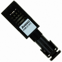
HFBR-2119TZ Avago Technologies US Inc., HFBR-2119TZ Datasheet - Page 7

HFBR-2119TZ
Manufacturer Part Number
HFBR-2119TZ
Description
RECEIVER FIBER OPTIC ST 266MBD
Manufacturer
Avago Technologies US Inc.
Datasheet
1.HFBR-2119TZ.pdf
(12 pages)
Specifications of HFBR-2119TZ
Voltage - Supply
4.5 V ~ 5.5 V
Power - Minimum Receivable
-28dBm
Current - Supply
185mA
Applications
General Purpose
Function
Fiber Channel applications or for general purpose fiber optic data link transmission
Product
Receiver
Data Rate
266 MBd
Wavelength
1380 nm (Max)
Maximum Rise Time
2.2 ns
Maximum Fall Time
2.2 ns
Pulse Width Distortion
0.97 ns
Maximum Output Current
50 mA
Operating Supply Voltage
4.5 V to 5.5 V
Maximum Operating Temperature
+ 70 C
Minimum Operating Temperature
0 C
Package / Case
DIP With Connector
Lead Free Status / RoHS Status
Lead free / RoHS Compliant
For Use With
Multimode Glass
Lead Free Status / RoHS Status
Lead free / RoHS Compliant, Lead free / RoHS Compliant
Other names
516-2051
Available stocks
Company
Part Number
Manufacturer
Quantity
Price
Company:
Part Number:
HFBR-2119TZ
Manufacturer:
Avago Technologies US Inc.
Quantity:
135
Regulatory Compliance
These data link modules are
intended to enable commercial
system designers to develop
equipment that complies with the
various international regulations
governing certification of Infor-
mation Technology Equipment.
Additional information is available
from your Avago sales
representative.
All HFBR-1119TZ LED trans-
mitters are classified as IEC-825-1
Accessible Emission Limit (AEL)
Class 1 based upon the current
proposed draft scheduled to go
into effect on January 1, 1997. AEL
Class 1 LED devices are consid-
ered eye safe. See Application Note
1094, LED Device Classifications
with Respect to AEL Values as
Defined in the IEC 825-1
Standard and the European
EN60825-1 Directive.
The material used for the housing
in the HFBR-1119TZ/-2119TZ
series is Ultem 2100 (GE). Ultem
2100 is recognized for a UL
flammability rating of 94V-0 (UL
File Number E121562) and the
CSA (Canadian Standards
Association) equivalent (File
Number LS88480).
7
Figure 8. Typical transmitter output optical spectral
width (FWHM) vs. transmitter output optical center
wavelength and rise/fall times.
Figure 9. HFBR-2119TZ receiver relative input
optical power vs. eye sampling time position.
CONDITIONS:
1. T
2. V
3. INPUT OPTICAL RISE/FALL TIMES = 1.0/1.9 ns
4. INPUT OPTICAL POWER IS NORMALIZED
5. NOTES 11 AND 12 APPLY
TO CENTER OF DATA SYMBOL
5
4
3
2
1
0
A
-1.5
CC
= 25 °C
EYE SAMPLING TIME POSITION – ns
220
200
180
160
140
120
100
= 5 Vdc
80
60
HFBR-1119TZ TYPICAL TRANSMITTER TEST
RESULTS OF c,
AND COMPLY WITH THE ALLOWED SPECTRAL
WIDTH AS A FUNCTION OF CENTER WAVELENGTH
FOR VARIOUS RISE AND FALL TIMES.
1280
c – TRANSMITTER OUTPUT OPTICAL
-1
CENTER WAVELENGTH – nm
1300
-0.5
1320
0
TRANSMITTER
OUTPUT OPTICAL
RISE TIMES – ns
AND t
0.5
1340
r
ARE CORRELATED
1
1360
1.5
1380
t
t
t
t
t
r
r
r
r
r
= 1.8 ns
= 1.9 ns
= 2.0 ns
= 2.1 ns
= 2.2 ns


