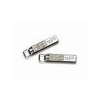
AFBR-5715LZ Avago Technologies US Inc., AFBR-5715LZ Datasheet - Page 5

AFBR-5715LZ
Manufacturer Part Number
AFBR-5715LZ
Description
TXRX OPTICAL SFP DMI STD LATCH
Manufacturer
Avago Technologies US Inc.
Specifications of AFBR-5715LZ
Data Rate
1.25Gbps
Wavelength
850nm
Applications
Ethernet
Voltage - Supply
3.135 V ~ 3.465 V
Connector Type
LC Duplex
Mounting Type
SFP
Function
Designed for those applications requiring DMI features.
Product
Transceiver
Maximum Rise Time
0.26 ns/0.22 ns (Typ)
Maximum Fall Time
0.26 ns/0.22 ns (Typ)
Pulse Width Distortion
0.227 ns (Max)/0.266 ns (Max)
Operating Supply Voltage
3.135 V to 3.465 V
Maximum Operating Temperature
+ 85 C
Minimum Operating Temperature
- 10 C
Package / Case
SFP
Optical Fiber Type
TX/RX
Data Transfer Rate
1250MBd
Optical Rise Time
0.26/0.22ns
Optical Fall Time
0.26/0.22ns
Jitter
0.227/0.266ns
Operating Temperature Classification
Commercial
Peak Wavelength
850nm
Package Type
SFP
Operating Supply Voltage (min)
3.135V
Operating Supply Voltage (typ)
3.3V
Operating Supply Voltage (max)
3.465V
Operating Temp Range
-10C to 85C
Mounting
Snap Fit To Panel
Pin Count
20
Lead Free Status / RoHS Status
Lead free / RoHS Compliant
Lead Free Status / RoHS Status
Lead free / RoHS Compliant, Lead free / RoHS Compliant
As an enhancement to the conventional SFP interface
defined in SFF-8074i, the AFBR-5715Z family is compliant
to SFF-8472 (digital diagnostic interface for optical
transceivers). This new digital diagnostic information is
stored in bytes 0-255 at memory address 0xA2.Using
the 2-wire serial interface defined in the MSA, the AFBR-
5715Z provides real time temperature, supply voltage,
laser bias current, laser average output power and
received input power. These parameters are internally
calibrated, per the MSA.
The digital diagnostic interface also adds the ability to
disable the transmitter (TX_DISABLE), monitor for
Transmitter Faults (TX_FAULT), and monitor for Receiver
Loss of Signal (RX_LOS).
The new diagnostic information provides the
opportunity for Predictive Failure Identification,
Compliance Prediction, Fault Isolation and Component
Monitoring.
Predictive Failure Identification
The predictive failure feature allows a host to identify
potential link problems before system performance is
impacted. Prior identification of link problems enables
a host to service an application via “fail over” to a
redundant link or replace a suspect device, maintaining
system uptime in the process. For applications where
ultra-high system uptime is required, a digital SFP
provides a means to monitor two real-time laser metrics
associated with observing laser degradation and
predicting failure: average laser bias current (Tx_Bias)
and average laser optical power (Tx_Power).
Compliance Prediction
Compliance prediction is the ability to determine if an
optical transceiver is operating within its operating and
environmental requirements. AFBR-5715Z devices
provide real-time access to transceiver internal supply
voltage and temperature, allowing a host to identify
Figure 4. MSA required power supply filter.
5
SFP MODULE
V
V
CC
CC
R
T
0.1 µF
0.1 µF
10 µF
HOST BOARD
1 µH
1 µH
0.1 µF
potential component compliance issues. Received
optical power is also available to assess compliance of a
cable plant and remote transmitter. When operating out
of requirements, the link cannot guarantee error free
transmission.
Fault Isolation
The fault isolation feature allows a host to quickly
pinpoint the location of a link failure, minimizing
downtime. For optical links, the ability to identify a fault
at a local device, remote device or cable plant is crucial
to speeding service of an installation. AFBR-5715Z real-
time monitors of Tx_Bias, Tx_Power, Vcc, Temperature
and Rx_Power can be used to assess local transceiver
current operating conditions. In addition, status flags
Tx_Disable and Rx Loss of Signal (LOS) are mirrored in
memory and available via the two-wire serial interface.
Component Monitoring
Component evaluation is a more casual use of the
AFBR-5715Z real-time monitors of Tx_Bias, Tx_Power,
Vcc, Temperature and Rx_Power. Potential uses are as
debugging aids for system installation and design, and
transceiver parametric evaluation for factory or field
qualification. For example, temperature per module can
be observed in high density applications to facilitate
thermal evaluation of blades, PCI cards and systems.
Required Host Board Components
The MSA power supply noise rejection filter is required
on the host PCB to meet data sheet performance. The
MSA filter incorporates an inductor which should be
rated 400 mADC and 1 Ω series resistance or better. It
should not be replaced with a ferrite. The required filter
is illustrated in Figure 4.
The MSA also specifies that 4.7 K to 10 KΩ pull-up
resistors for TX_FAULT, LOS, and MOD_DEF0,1,2 are
required on the host PCB.
10 µF
3.3 V


