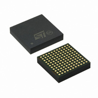
SPDC12L00010 STMicroelectronics, SPDC12L00010 Datasheet - Page 18

SPDC12L00010
Manufacturer Part Number
SPDC12L00010
Description
IC BUCK ADJ 10A 121LGA
Manufacturer
STMicroelectronics
Type
Point of Load (POL) Non-Isolated with UVLOr
Datasheet
1.SPDC12L00010.pdf
(29 pages)
Specifications of SPDC12L00010
Output
0.6 ~ 5V
Number Of Outputs
1
Power (watts)
50W
Mounting Type
Surface Mount
Voltage - Input
1.8 ~ 14V
Package / Case
121-LGA
1st Output
0.6 ~ 5 VDC @ 10A
Size / Dimension
0.59" L x 0.59" W x 0.11" H (15mm x 15mm x 2.8mm)
Power (watts) - Rated
50W
Operating Temperature
-40°C ~ 85°C
Efficiency
93%
Current - Output
10A
Voltage - Output
0.6 ~ 5 V
Frequency - Switching
729kHz
Synchronous Rectifier
No
Output Voltage
0.6 V to 5 V
Output Current
0 A to 10 A
Input Voltage
1.8 V to 14 V
Supply Current
65 mA
Switching Frequency
729 KHz
Maximum Operating Temperature
+ 85 C
Minimum Operating Temperature
- 40 C
Lead Free Status / RoHS Status
Lead free / RoHS Compliant
3rd Output
-
2nd Output
-
Lead Free Status / Rohs Status
Lead free / RoHS Compliant
Other names
497-9072
Available stocks
Company
Part Number
Manufacturer
Quantity
Price
Company:
Part Number:
SPDC12L00010
Manufacturer:
ADI
Quantity:
13
Application information
5.4
5.5
18/29
Soft-start
The soft-start phase begins when both VCC and VIN raise above their turn-on thresholds,
otherwise the SS_INL pin is internally shorted to SGND.
A ramp is generated at SS_INL pin during start-up, charging the external capacitor C
an internal current generator.
The initial value for this current is 30 μA and it charges the capacitor up to 0.5 V, after that, it
is reduced to 10 μA until the final charge value approximately 4 V.
In the meanwhile, the controller internal voltage reference raises to its final value, following
the SS_INL pin voltage slope.
During soft-start, the module provides a constant current protection, limiting the output
current at the maximum value, without entering in HICCUP mode.
If there is not current limitation, the output voltage slope follows the SS_INL pin slope.
The output voltage rise time, can be set choosing proper C
The soft-start phase ends when the SS_INL pin voltage reaches 3.5 V.
A capacitor C
suitable for Co = 10000 μF max. output capacitor;
in this condition and with 10 A output current resistor load, the output voltage rise time is
around 5ms, but the complete soft-start time is around 10ms.
Using the minimum output capacitor Co = 660 μF and with 10 A resistor load, the output
voltage rise time is around 2 ms.
Multiple units synchronization
Using more than one unit on the same circuit, it is possible to synchronize the switching
frequency oscillators, connecting all SYNC (pin L6) together.
The device with the higher switching frequency will be the Master, while the other will be the
Slaves.
The best way to synchronize two or more devices is to set same switching frequency, in any
case, the switching frequencies can differ for a maximum of 50% of the lowest one.
Using and external clock signal, to synchronize one or more devices working at a different
switching frequency, it is recommended to follow the below formula:
The phase shift between master and slaves is approximately 180°.
SS
= 3 3 nF is present on the module, to perform a minimum soft-start time,
Doc ID 15103 Rev 3
f
sw
≤
f
ext
≤
1.3f
sw
SS
value.
SPDC12L00010
SS
with


