QF4A512-PA Quickfilter Technologies LLC, QF4A512-PA Datasheet
QF4A512-PA
Specifications of QF4A512-PA


Related parts for QF4A512-PA


QF4A512-PA Summary of contents
Page 1
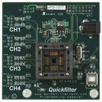
... Programming Adapter User’s Guide Socket power switch, switch off when changing parts Connects signals DC Jack +5V to +12V 2.1mm Tip from the development positive, board board added to development board Figure 1 QF4A512-PA USER’S GUIDE Push down on both sides of socket to change parts not needed if socket www.quickfiltertech.com ...
Page 2
... Example Mouser# 412-106054 6VDC/500mA Manufacturer is Xicon, price is approximately $5. The DC supply can vary from +5VDC to +9VDC. (Note: This voltage will show up in the prototyping area but not injury the development board) Rev A1, July 06 Programming Adapter User’s Guide Figure 2 2 QF4A512-PA www.quickfiltertech.com ...
Page 3
... Step 2: Make sure the power to the socket is “off” this done by pushing SW1 until the red light is OFF. Rev A1, July 06 Programming Adapter User’s Guide Adding the three additional headers brings the signals from the BNC connectors up to the programming adapter board. Figure 3 3 QF4A512-PA Align the programming board as shown when plugging it into the development board www.quickfiltertech.com ...
Page 4
... PIN1. See figure 4. Step 4: Push SW1 so that the red LED is ON. See Figure 5 Rev A1, July 06 Programming Adapter User’s Guide Make sure Pin1 lines up with the socket Pin1 Figure 4 Figure 5 4 QF4A512-PA Red light should be OFF when changing parts www.quickfiltertech.com ...
Page 5
... Step 6: Select “View” from the upper left options, select “Preferences”, check the box advanced features. Step 7: Choose “3-Control”, check the box “Use Programming Adapter”, Click “Yes” for switching to the Programming Adapter Board. Rev A1, July 06 Programming Adapter User’s Guide 5 QF4A512-PA www.quickfiltertech.com ...
Page 6
... Make sure to switch power off to the socket by depressing SW1. Step 10: Remove the programmed part, put the next QF4A512 to be programmed in the socket taken note of the correct Pin 1 orientation. Step 11: Push SW1 on so that the red LED is ON. Rev A1, July 06 Programming Adapter User’s Guide 6 QF4A512-PA www.quickfiltertech.com ...
Page 7
... AC coupled offset can exist. The clock can be a sine wave, or square wave. 9) List of Test Point Definitions: TP1 = +5V from DC wall adapter. TP2 = +3.3V from on board regulator. TP3 = +1.8V from on board regulator. TP22 = External clock input. GND = Ground point for external clock and voltage measurement. Rev A1, July 06 Programming Adapter User’s Guide 7 QF4A512-PA www.quickfiltertech.com ...
Page 8
... TP3 3V3 VIN VOUT C69 5 4 GND BY P 0.1uF C65 0603 C66 + 10uF 0.01 uF TPS79418DGNT 0603 Ultra Low Noise 250mA www.quickfiltertech.com QF4A512-PA 1V8 C8 0.1uF 0603 0805 3V3 C13 0.1uF 0603 SPI DIN 5 6 DOUT 7 8 CS1 CS2 PLUG 7X2 1V8 C68 3 ...
Page 9
... Quickfilter, the Quickfilter logo and combinations thereof, are trademarks of Quickfilter Technologies, Inc. Other product names used in this publication are for identification purposes only and may be trademarks of their respective companies. Rev A1, July 06 Programming Adapter Kit User’s Guide © 2006 Quickfilter Technologies, Inc. All rights reserved. 9 QF4A512-PA www.quickfiltertech.com ...