QF4A512-PA Quickfilter Technologies LLC, QF4A512-PA Datasheet - Page 3
QF4A512-PA
Manufacturer Part Number
QF4A512-PA
Description
ADAPTER PROG FOR QF4A512-DK
Manufacturer
Quickfilter Technologies LLC
Specifications of QF4A512-PA
Accessory Type
Programming Adapter
For Use With/related Products
QF4A512-DK
For Use With
686-1004 - KIT DEV FOR QF4A512
Lead Free Status / RoHS Status
Contains lead / RoHS non-compliant
Other names
686-1005


4) Plugging in the adapter board:
5) Input level and protection scheme:
6) Programming example:
Rev A1, July 06
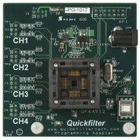
See figure 3 for alignment. The QF4A512 programming adapter should be pushed down evenly not at an angle.
Note, by adding the 3 additional headers to the development board signals will be brought up to the programming
adapter board through J1-J4. See below.
The QF4A512 programming adapter is DC coupled with input voltage protection only. With no modifications the
largest signal is 2Vpp AC coupled. Voltages larger than 3.0V will activate the internal protection diodes which are
series limited with 100ohms. These resistors can be changed to simulate the target system including a spot to add
AC coupling.
Step 1: Plug in the USB cable to the development board. Make sure the programming adapter board is powered
Step 2: Make sure the power to the socket is “off” this done by pushing SW1 until the red light is OFF.
either from the development board or through the AC Adapter plugged into CN4.
Note: R2,R6,R11,R15
for the PA board and
ended configuration
development board
create the single
Programming Adapter User’s Guide
headers brings the signals from the
programming adapter board.
Adding the three additional
BNC connectors up to the
3
Figure 3
Align the programming
board as shown when
development board
plugging it into the
www.quickfiltertech.com
QF4A512-PA
Related parts for QF4A512-PA
Image
Part Number
Description
Manufacturer
Datasheet
Request
R

Part Number:
Description:
KIT DEV FOR QF4A512
Manufacturer:
Quickfilter Technologies LLC
Datasheet:

Part Number:
Description:
KIT DEV FOR QF1F512
Manufacturer:
Quickfilter Technologies LLC
Datasheet:

Part Number:
Description:
KIT DEV FOR QF1DA512
Manufacturer:
Quickfilter Technologies LLC
Datasheet:

Part Number:
Description:
DEV KIT QF1D512 AUDIO MOJO
Manufacturer:
Quickfilter Technologies LLC

Part Number:
Description:
IC PROG SIGNAL CONV 4CH 32LQFP
Manufacturer:
Quickfilter Technologies LLC

Part Number:
Description:
IC FILTER DGTL PROGBL 16-VQFN
Manufacturer:
Quickfilter Technologies LLC
Datasheet:

Part Number:
Description:
IC SAVFIRE DGTL FILTER 1CH 16QFN
Manufacturer:
Quickfilter Technologies LLC

Part Number:
Description:
ADAPTER PROTOTYPING FOR QF1D512
Manufacturer:
Quickfilter Technologies LLC
Datasheet:

Part Number:
Description:
BOARD MSP-MOJO + EXPANSION HEADR
Manufacturer:
Quickfilter Technologies LLC
Datasheet:

Part Number:
Description:
REF DESIGN BLUETOOTH STER HDSET
Manufacturer:
Quickfilter Technologies LLC
Datasheet:
Part Number:
Description:
IC PROG SIGNAL CONV 4CH 32LQFP
Manufacturer:
Quickfilter Technologies LLC
Part Number:
Description:
IC FILTER DGTL PROGBL 16-VQFN
Manufacturer:
Quickfilter Technologies LLC
Datasheet:
Part Number:
Description:
IC SAVFIRE DGTL FILTER 1CH 16QFN
Manufacturer:
Quickfilter Technologies LLC