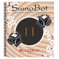
122-27400 Parallax Inc, 122-27400 Datasheet - Page 33

122-27400
Manufacturer Part Number
122-27400
Description
MANUAL FOR SUMOBOT
Manufacturer
Parallax Inc
Datasheet
1.27400.pdf
(77 pages)
Specifications of 122-27400
Accessory Type
Manual
Product
Microcontroller Accessories
Lead Free Status / RoHS Status
Contains lead / RoHS non-compliant
For Use With/related Products
SumoBot®
Lead Free Status / RoHS Status
Lead free / RoHS Compliant, Contains lead / RoHS non-compliant
- Current page: 33 of 77
- Download datasheet (2Mb)
Chapter 3: SumoBot Sensors and Border Detection · Page 23
Chapter 3: SumoBot Sensors and Border Detection
Once the SumoBot is moving, the next task is to scan the playing surface to make sure
that it doesn't drive itself out of the ring. The task is accomplished by two specialized
line detection sensors called QTIs. The QTI uses a reflective infrared sensor to allow the
SumoBot to "look" for the ring's border.
LINE SENSOR THEORY
The Parallax QTI uses a QRD1114 infrared (IR) reflective sensor to determine the
reflectivity of the surface below it. When the SumoBot is over the black playing field or
start lines (Shikiri), the reflectivity is very low; when the QTI is over the white border
(Tawara), the reflectivity is very high and will cause a different reading from the sensor.
Figure 3.1 shows the schematic for the Parallax QTI line sensor.
Figure 3.1: QTI Line Sensor Schematic
The QTI sensor is activated by placing 5V (Vdd) on the W pin. This will cause current to
flow through the 470 Ω resistor to the LED side of the QRD1114. IR light reflecting of
the surface below will cause a change in the ability for current to flow through the
phototransistor side of the QRD1114. The transistor, in effect, behaves like an IR
controlled resistance.
The BASIC Stamp has a specific command designed to read a variable resistance called
RCTIME . When coupled with a capacitor, the BASIC Stamp can measure a variable
resistance by timing the charge or discharge rate of the connected capacitor.
Related parts for 122-27400
Image
Part Number
Description
Manufacturer
Datasheet
Request
R

Part Number:
Description:
GUIDE STUDENT PROCESS CONTROL
Manufacturer:
Parallax Inc
Datasheet:

Part Number:
Description:
GUIDE STUDENT SMART SENSORS
Manufacturer:
Parallax Inc
Datasheet:

Part Number:
Description:
MANUAL PROPELLER
Manufacturer:
Parallax Inc
Datasheet:

Part Number:
Description:
LEAD WIRES FLYING CABLE III/IV
Manufacturer:
Xilinx Inc
Datasheet:

Part Number:
Description:
BOARD ADAPTER AND FLY LEADS
Manufacturer:
Xilinx Inc
Datasheet:

Part Number:
Description:
PLATFORM CABLE USB II
Manufacturer:
Xilinx Inc
Datasheet:

Part Number:
Description:
KIT STARTER COOLRUNNER-II BUNDLE
Manufacturer:
Xilinx Inc
Datasheet:

Part Number:
Description:
Microcontroller Modules & Accessories DISCONTINUED BY PARALLAX
Manufacturer:
Parallax Inc

Part Number:
Description:
Microcontroller Modules & Accessories DISCONTINUED BY PARALLAX
Manufacturer:
Parallax Inc

Part Number:
Description:
BOOK UNDERSTANDING SIGNALS
Manufacturer:
Parallax Inc
Datasheet:

Part Number:
Description:
BOARD EXPERIMENT+LCD NX-1000
Manufacturer:
Parallax Inc
Datasheet:

Part Number:
Description:
IC MCU 2K FLASH 50MHZ SO-18
Manufacturer:
Parallax Inc
Datasheet:


