130-28176 Parallax Inc, 130-28176 Datasheet - Page 140
130-28176
Manufacturer Part Number
130-28176
Description
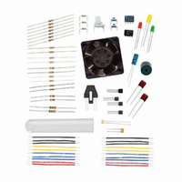
KIT PARTS PROCESS CONTROL
Manufacturer
Parallax Inc
Specifications of 130-28176
Accessory Type
Education Kit
Product
Microcontroller Accessories
Lead Free Status / RoHS Status
Contains lead / RoHS non-compliant
For Use With/related Products
Board of Education Full Kit
Lead Free Status / RoHS Status
Lead free / RoHS Compliant, Contains lead / RoHS non-compliant


Page 130 · Process Control
CONCLUSION
The opto-reflective switch combines an emitter (LED) and detector (phototransistor) in a
single package for the detection of near-range objects. The phototransistor acts similar to
a BJT transistor, except that the base current is controlled with light instead of voltage.
Other optical sensors use photodiodes or PIN diodes that have much better switching
action.
Using the opto-reflective switch requires providing sufficient current to the LED to emit
light and conditioning the output to produce a voltage when an object reflects the emitted
light to the detector. The sizing of the collector resistance is critical in achieving the
voltage swing required for input to the BASIC Stamp. Increased switching action can be
obtained by using a Darlington Pair arrangement, decreasing the size of the collector
resistance needed. A small current from the phototransistor is used to bias a second
transistor acting as a switch.
Sequential processes perform a specific sequence of actions based on input or timed
events. In this chapter, the opto-reflective switch and pushbuttons were used for events
such as performing a batch mix operation or operating a diverter for box loading.
Counting with an opto-reflective switch or other detectors can be either very slow (object
counting) or very fast (tachometer). There are issues involved in both types, including
the need to use edge detection, increase response, and determine the resolution needed.
Resolution of high speed counting can be performed by either increasing how long a
count occurs (which decreases the program scan time) or by performing a greater number
of counts per revolution, based on the encoder used (which requires greater detector
response time).
One last point concerns the use of IR emitters and detectors used with the Boe-Bot robot
and TV remote controls. These are more complex detectors in that they will only respond
to infrared light that is cycling on and off at roughly 38 kHz.
SOLUTIONS TO CHAPTER 4 CHALLENGES
Challenge 4-1 Solution
Results are dependent on materials tested. Which colors absorbed more infrared light?
Did shiny material reflect better?
Related parts for 130-28176
Image
Part Number
Description
Manufacturer
Datasheet
Request
R

Part Number:
Description:
KIT PROPELLER EDU PROJECT PARTS
Manufacturer:
Parallax Inc
Datasheet:

Part Number:
Description:
KIT PARTS SMART SENSORS
Manufacturer:
Parallax Inc
Datasheet:


Part Number:
Description:
Microcontroller Modules & Accessories DISCONTINUED BY PARALLAX
Manufacturer:
Parallax Inc

Part Number:
Description:
BOOK UNDERSTANDING SIGNALS
Manufacturer:
Parallax Inc
Datasheet:


Part Number:
Description:
COMPETITION RING FOR SUMOBOT
Manufacturer:
Parallax Inc
Datasheet:


Part Number:
Description:
TEXT INFRARED REMOTE FOR BOE-BOT
Manufacturer:
Parallax Inc
Datasheet:
Part Number:
Description:
Microcontroller Modules & Accessories DISCONTINUED BY PARALLAX
Manufacturer:
Parallax Inc
Part Number:
Description:
BOOK UNDERSTANDING SIGNALS
Manufacturer:
Parallax Inc
Datasheet:
Part Number:
Description:
BOARD EXPERIMENT+LCD NX-1000
Manufacturer:
Parallax Inc
Datasheet:
Part Number:
Description:
IC MCU 2K FLASH 50MHZ SO-18
Manufacturer:
Parallax Inc
Datasheet: