130-28176 Parallax Inc, 130-28176 Datasheet - Page 89
130-28176
Manufacturer Part Number
130-28176
Description
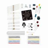
KIT PARTS PROCESS CONTROL
Manufacturer
Parallax Inc
Specifications of 130-28176
Accessory Type
Education Kit
Product
Microcontroller Accessories
Lead Free Status / RoHS Status
Contains lead / RoHS non-compliant
For Use With/related Products
Board of Education Full Kit
Lead Free Status / RoHS Status
Lead free / RoHS Compliant, Contains lead / RoHS non-compliant


Chapter 3: Digital Input Conditioning · Page 79
voltage and the resistance of the collector for the configuration studied. The DC Load
Line is a graphical representation of output voltage and collector current over the linear
range.
The value of R
in a common-emitter configuration determines the saturation current,
C
and thus, the base current required to drive the BJT into saturation. The higher the value
of R
the more sensitive the transistor will be to base current. But high values of R
also
C
C
limit response and switching speeds of the transistor. The maximum power dissipated by
the transistor occurs when it is conducting ½ of saturation current, which leads to heating.
SOLUTIONS TO CHAPTER 3 CHALLENGES
Challenge 3-1 Solution
When the potentiometer supply leads are reversed, rotation will result in the opposite
direction of voltage change as compared to previously. For example, when rotated clock-
wise, the wiper of the potentiometer will be closer to Vdd as opposed to Vss previously.
Related parts for 130-28176
Image
Part Number
Description
Manufacturer
Datasheet
Request
R

Part Number:
Description:
KIT PROPELLER EDU PROJECT PARTS
Manufacturer:
Parallax Inc
Datasheet:

Part Number:
Description:
KIT PARTS SMART SENSORS
Manufacturer:
Parallax Inc
Datasheet:


Part Number:
Description:
Microcontroller Modules & Accessories DISCONTINUED BY PARALLAX
Manufacturer:
Parallax Inc

Part Number:
Description:
BOOK UNDERSTANDING SIGNALS
Manufacturer:
Parallax Inc
Datasheet:


Part Number:
Description:
COMPETITION RING FOR SUMOBOT
Manufacturer:
Parallax Inc
Datasheet:


Part Number:
Description:
TEXT INFRARED REMOTE FOR BOE-BOT
Manufacturer:
Parallax Inc
Datasheet:
Part Number:
Description:
Microcontroller Modules & Accessories DISCONTINUED BY PARALLAX
Manufacturer:
Parallax Inc
Part Number:
Description:
BOOK UNDERSTANDING SIGNALS
Manufacturer:
Parallax Inc
Datasheet:
Part Number:
Description:
BOARD EXPERIMENT+LCD NX-1000
Manufacturer:
Parallax Inc
Datasheet:
Part Number:
Description:
IC MCU 2K FLASH 50MHZ SO-18
Manufacturer:
Parallax Inc
Datasheet: