130-28176 Parallax Inc, 130-28176 Datasheet - Page 61
130-28176
Manufacturer Part Number
130-28176
Description
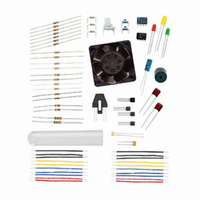
KIT PARTS PROCESS CONTROL
Manufacturer
Parallax Inc
Specifications of 130-28176
Accessory Type
Education Kit
Product
Microcontroller Accessories
Lead Free Status / RoHS Status
Contains lead / RoHS non-compliant
For Use With/related Products
Board of Education Full Kit
Lead Free Status / RoHS Status
Lead free / RoHS Compliant, Contains lead / RoHS non-compliant


Saving digital input is performed within the routine to read the ADC, in an attempt to
read both the ADC and digital input at the same time. The ADC value and the digital
value may not track perfectly depending on how quickly the analog level changes.
Challenge 3-1: Reversing the Potentiometer Supply Voltage
What has changed when rotating the potentiometer? Explain why this change has
occurred. (Hint: Refer to Figure 3-3a, and consider what occurs when Vss and Vdd are
swapped).
ACTIVITY #2: NIGHT-LIGHT PROCESS
The input of the BASIC Stamp changing between HIGH and LOW at a fixed voltage can
provide a simple means of control using analog signals. The input simply needs to go
above and below the threshold level for the controller.
In this activity, a photoresistor will be added to the bottom of the variable resistor in the
ADC circuit from Activity 1. This modified circuit creates a light-controlled voltage
divider input to the BS2 for control of a light (the LED) at a certain level of darkness.
Parts Required
Circuit from Activity #1 (Figure 3-1 on page 46)
(1) Photoresistor
√
√
√
√
√
√
√
√
√
Modify the circuit as shown in Figure 3-4 by adding the photoresistor between
the potentiometer and Vss. Do not modify the ADC or LED portions of the
circuit.
Re-run the program DataMonitoring.bs2, if needed.
Close the Debug Terminal.
Run StampPlot macro sic_pc_data_monitoring.spm.
Connect and plot.
Allow the photoresistor to be exposed to ‘daylight levels’ of light.
Adjust the potentiometer for a daylight voltage of 1.0 V.
Note the direction of rotation needed to achieve an increasing voltage.
Reverse the Vdd and Vss connections to the potentiometer.
Related parts for 130-28176
Image
Part Number
Description
Manufacturer
Datasheet
Request
R

Part Number:
Description:
KIT PROPELLER EDU PROJECT PARTS
Manufacturer:
Parallax Inc
Datasheet:

Part Number:
Description:
KIT PARTS SMART SENSORS
Manufacturer:
Parallax Inc
Datasheet:


Part Number:
Description:
Microcontroller Modules & Accessories DISCONTINUED BY PARALLAX
Manufacturer:
Parallax Inc

Part Number:
Description:
BOOK UNDERSTANDING SIGNALS
Manufacturer:
Parallax Inc
Datasheet:


Part Number:
Description:
COMPETITION RING FOR SUMOBOT
Manufacturer:
Parallax Inc
Datasheet:


Part Number:
Description:
TEXT INFRARED REMOTE FOR BOE-BOT
Manufacturer:
Parallax Inc
Datasheet:
Part Number:
Description:
Microcontroller Modules & Accessories DISCONTINUED BY PARALLAX
Manufacturer:
Parallax Inc
Part Number:
Description:
BOOK UNDERSTANDING SIGNALS
Manufacturer:
Parallax Inc
Datasheet:
Part Number:
Description:
BOARD EXPERIMENT+LCD NX-1000
Manufacturer:
Parallax Inc
Datasheet:
Part Number:
Description:
IC MCU 2K FLASH 50MHZ SO-18
Manufacturer:
Parallax Inc
Datasheet: