130-28176 Parallax Inc, 130-28176 Datasheet - Page 95
130-28176
Manufacturer Part Number
130-28176
Description
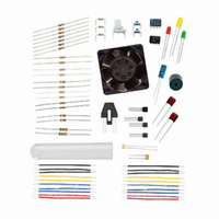
KIT PARTS PROCESS CONTROL
Manufacturer
Parallax Inc
Specifications of 130-28176
Accessory Type
Education Kit
Product
Microcontroller Accessories
Lead Free Status / RoHS Status
Contains lead / RoHS non-compliant
For Use With/related Products
Board of Education Full Kit
Lead Free Status / RoHS Status
Lead free / RoHS Compliant, Contains lead / RoHS non-compliant


The IR LED emitter and phototransistor are combined in a single package. The pair are
angled for maximum reflection from a surface at a distance of 0.15 inches (3.8 mm) or
about 1/6 of an inch. This non-contact switch responds to an object passing in front of its
window within the range of detection.
From the study of transistors in Chapter 3, a correct configuration is required for this
switch to be sensed as a digital input.
The IR LED is rated at a maximum current of 40 mA. Given that the IR LED drops
around 1.5 V, this leaves 3.5 V for calculating the size of the resistor needed to limit
current to the IR LED.
A 100 Ω current-limiting resistor will be used. Since the base current (dependent on IR
radiation) and gain are not quantifiable, determining collector current requires some
experimentation.
Parts Required
(1) Resistor – 100 Ω
(2) Resistors – 220 Ω
(1) Resistor – 10 kΩ
(1) Resistor – 100 kΩ
(1) Resistor – 1 MΩ
(1) Opto-Reflective Switch – QRB1114
(1) ADC0831
(1) LED – Red
•
•
•
•
The uncommitted collector will require a pull-up.
The collector resistor must be sized such that the output has transitions between
light and dark conditions above and below the BASIC Stamp threshold voltage.
The emitter is connected to ground.
Sufficient base current exists. In this case it would be due to IR LED emissions
reflecting off an object.
R = V/I = (Vdd − V
LED
)/I
LED
= (5.0 V−1.5 V)/40 mA = 87.5 Ω.
Related parts for 130-28176
Image
Part Number
Description
Manufacturer
Datasheet
Request
R

Part Number:
Description:
KIT PROPELLER EDU PROJECT PARTS
Manufacturer:
Parallax Inc
Datasheet:

Part Number:
Description:
KIT PARTS SMART SENSORS
Manufacturer:
Parallax Inc
Datasheet:


Part Number:
Description:
Microcontroller Modules & Accessories DISCONTINUED BY PARALLAX
Manufacturer:
Parallax Inc

Part Number:
Description:
BOOK UNDERSTANDING SIGNALS
Manufacturer:
Parallax Inc
Datasheet:


Part Number:
Description:
COMPETITION RING FOR SUMOBOT
Manufacturer:
Parallax Inc
Datasheet:


Part Number:
Description:
TEXT INFRARED REMOTE FOR BOE-BOT
Manufacturer:
Parallax Inc
Datasheet:
Part Number:
Description:
Microcontroller Modules & Accessories DISCONTINUED BY PARALLAX
Manufacturer:
Parallax Inc
Part Number:
Description:
BOOK UNDERSTANDING SIGNALS
Manufacturer:
Parallax Inc
Datasheet:
Part Number:
Description:
BOARD EXPERIMENT+LCD NX-1000
Manufacturer:
Parallax Inc
Datasheet:
Part Number:
Description:
IC MCU 2K FLASH 50MHZ SO-18
Manufacturer:
Parallax Inc
Datasheet: