UM245R FTDI, Future Technology Devices International Ltd, UM245R Datasheet - Page 19
UM245R
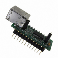
Manufacturer Part Number
UM245R
Description
MODULE USB-PAR FIFO TTL 24-DIP
Manufacturer
FTDI, Future Technology Devices International Ltd
Datasheet
1.UM245R.pdf
(27 pages)
Specifications of UM245R
Main Purpose
Interface, USB 2.0 to Parallel FIFO Bridge
Embedded
No
Utilized Ic / Part
FT245R
Primary Attributes
300kBps to 1MBps USB to parallel FIFO via 4-Wire Interface
Secondary Attributes
Royalty-Free Drivers
Lead Free Status / RoHS Status
Lead free / RoHS Compliant
Other names
768-1020


7
7.1 BUS Powered Configuration
Figure 7.1 Bus Powered Configuration
Figure 7.1 illustrates the UM245R in a typical USB bus powered design configuration. This can easily be
done by fitting the jumper link on J2, as shown above. The UM245R is supplied in this configuration by
default. A USB Bus Powered device gets its power from the USB bus. Basic rules for USB Bus power
devices are as follows:
Interfacing the UM245R module to a microcontroller (MCU), or other logic for a bus powered design
would be done in exactly the same way as for a self powered design (see
MCU would take its power supply from the USB bus (either the 5V on the USB pin, or the 3.3V on the 3V3
pin).
© Copyright 2009 Future Technology Devices International Ltd
i)
ii) On USB Suspend the device must draw no more than 500μA (2.5mA if remote wake-up is
iii) A Bus Powered High Power USB Device (one that draws more than 100mA) should use the
iv) A device that consumes more than 100mA cannot be plugged into a USB Bus Powered Hub.
v) No device can draw more that 500mA from the USB Bus.
Module Configurations
On plug-in to USB, the device must draw no more than 100mA.
enabled).
PWREN# pin to keep the current below 100mA on plug-in and 500μA/2.5mA on USB suspend.
UM245R USB - Parallel FIFO Development Module Datasheet Version 1.04
Document Reference No.: FT_000202
Section
Clearance No.: FTDI# 124
7.2), except that the
18
Related parts for UM245R
Image
Part Number
Description
Manufacturer
Datasheet
Request
R

Part Number:
Description:
IC USB TO SERIAL UART 32-QFN
Manufacturer:
FTDI, Future Technology Devices International Ltd

Part Number:
Description:
IC USB HOST CTLR VINCULUM 48LQFP
Manufacturer:
FTDI, Future Technology Devices International Ltd
Datasheet:

Part Number:
Description:
IC USB HOST VINCULUM-II 32QFN
Manufacturer:
FTDI, Future Technology Devices International Ltd
Datasheet:
Part Number:
Description:
IC USB HOST VINCULUM-II 32LQFN
Manufacturer:
FTDI, Future Technology Devices International Ltd
Datasheet:
Part Number:
Description:
IC USB HOST VINCULUM-II 48QFN
Manufacturer:
FTDI, Future Technology Devices International Ltd
Datasheet:
Part Number:
Description:
IC USB HOST VINCULUM-II 32LQFN
Manufacturer:
FTDI, Future Technology Devices International Ltd
Datasheet:
Part Number:
Description:
IC USB HOST VINCULUM-II 32QFN
Manufacturer:
FTDI, Future Technology Devices International Ltd
Datasheet:
Part Number:
Description:
IC USB HOST VINCULUM-II 48LQFP
Manufacturer:
FTDI, Future Technology Devices International Ltd
Datasheet:
Part Number:
Description:
IC USB HOST VINCULUM-II 48LQFP
Manufacturer:
FTDI, Future Technology Devices International Ltd
Datasheet:
Part Number:
Description:
IC USB HOST VINCULUM-II 48QFN
Manufacturer:
FTDI, Future Technology Devices International Ltd
Datasheet:
Part Number:
Description:
IC USB HOST CTLR VINCULUM 64QFN
Manufacturer:
FTDI, Future Technology Devices International Ltd
Datasheet:

Part Number:
Description:
IC USB HOST CTLR VINCULUM 64LQFP
Manufacturer:
FTDI, Future Technology Devices International Ltd
Datasheet:
Part Number:
Description:
IC USB HOST VINCULUM-II 64LQFP
Manufacturer:
FTDI, Future Technology Devices International Ltd
Datasheet:
Part Number:
Description:
IC USB HOST VINCULUM-II 64QFN
Manufacturer:
FTDI, Future Technology Devices International Ltd
Datasheet:

Part Number:
Description:
IC USB TO PARALLEL FIFO 28-SSOP
Manufacturer:
FTDI, Future Technology Devices International Ltd
Datasheet: