UM245R FTDI, Future Technology Devices International Ltd, UM245R Datasheet - Page 26
UM245R
Manufacturer Part Number
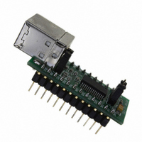
UM245R
Description
MODULE USB-PAR FIFO TTL 24-DIP
Manufacturer
FTDI, Future Technology Devices International Ltd
Datasheet
1.UM245R.pdf
(27 pages)
Specifications of UM245R
Main Purpose
Interface, USB 2.0 to Parallel FIFO Bridge
Embedded
No
Utilized Ic / Part
FT245R
Primary Attributes
300kBps to 1MBps USB to parallel FIFO via 4-Wire Interface
Secondary Attributes
Royalty-Free Drivers
Lead Free Status / RoHS Status
Lead free / RoHS Compliant
Other names
768-1020


Document Reference No.: FT_000202
UM245R USB - Parallel FIFO Development Module Datasheet Version 1.04
Clearance No.: FTDI# 124
Appendix A – List of Tables and Figures
List of Table
Table 4.1 Module Pin-Out Description .......................................................................................................... 9
Table 4.2 Jumper J1 Pin Description ............................................................................................................ 9
Table 4.3 Jumper J2 Pin Description ............................................................................................................ 9
Table 4.4 FIFO Read Cycle Timings ............................................................................................................ 10
Table 4.5 FIFO Write Cycle Timings ........................................................................................................... 11
Table 6.1 Absolute Maximum Ratings ........................................................................................................ 13
Table 6.2 Operating Voltage and Current ................................................................................................... 13
Table 6.3 FIFO Interface and Control Bus Pin Characteristics (VCCIO = 5.0V, Standard Drive Level) ........ 14
Table 6.4 FIFO Interface and Control Bus Pin Characteristics (VCCIO = 3.3V, Standard Drive Level) ........ 14
Table 6.5 FIFO Interface and Control Bus Pin Characteristics (VCCIO = 2.8V, Standard Drive Level) ........ 14
Table 6.6 FIFO Interface and Control Bus Pin Characteristics (VCCIO = 5.0V, High Drive Level) ............... 15
Table 6.7 FIFO Interface and Control Bus Pin Characteristics (VCCIO = 3.3V, High Drive Level) ............... 15
Table 6.8 FIFO Interface and Control Bus Pin Characteristics (VCCIO = 2.8V, High Drive Level) ............... 15
Table 6.9 RESET# and TEST Pin Characteristics ......................................................................................... 15
Table 6.10 USB I/O Pin (USBDP, USBDM) Characteristics ......................................................................... 16
Table 6.11 EEPROM Characteristics ........................................................................................................... 16
Table 6.12 Internal Clock Characteristics .................................................................................................. 17
Table 9.1 Default Internal EEPROM Configuration ..................................................................................... 23
List of Table
Figure 1.1 – UM245R USB to Parallel FIFO Development Module ................................................................. 1
Figure 4.1 Module Pin Out and Jumper Locations ........................................................................................ 7
Figure 4.2 FIFO Read Cycle ........................................................................................................................ 10
Figure 4.3 FIFO Write Cycle ....................................................................................................................... 11
Figure 5.1 UM245R Module Dimensions ..................................................................................................... 12
Figure 7.1 Bus Powered Configuration ...................................................................................................... 18
Figure 7.2 Self-Powered Configuration ...................................................................................................... 19
Figure 7.3 Bus Powered with Power Switching Configuration ................................................................... 20
Figure 7.4 USB Bus Powered 3.3V Logic Drive ........................................................................................... 21
Figure 8.1 Module Circuit Schematic .......................................................................................................... 22
© Copyright 2009 Future Technology Devices International Ltd
25
Related parts for UM245R
Image
Part Number
Description
Manufacturer
Datasheet
Request
R

Part Number:
Description:
IC USB TO SERIAL UART 32-QFN
Manufacturer:
FTDI, Future Technology Devices International Ltd

Part Number:
Description:
IC USB HOST CTLR VINCULUM 48LQFP
Manufacturer:
FTDI, Future Technology Devices International Ltd
Datasheet:

Part Number:
Description:
IC USB HOST VINCULUM-II 32QFN
Manufacturer:
FTDI, Future Technology Devices International Ltd
Datasheet:
Part Number:
Description:
IC USB HOST VINCULUM-II 32LQFN
Manufacturer:
FTDI, Future Technology Devices International Ltd
Datasheet:
Part Number:
Description:
IC USB HOST VINCULUM-II 48QFN
Manufacturer:
FTDI, Future Technology Devices International Ltd
Datasheet:
Part Number:
Description:
IC USB HOST VINCULUM-II 32LQFN
Manufacturer:
FTDI, Future Technology Devices International Ltd
Datasheet:
Part Number:
Description:
IC USB HOST VINCULUM-II 32QFN
Manufacturer:
FTDI, Future Technology Devices International Ltd
Datasheet:
Part Number:
Description:
IC USB HOST VINCULUM-II 48LQFP
Manufacturer:
FTDI, Future Technology Devices International Ltd
Datasheet:
Part Number:
Description:
IC USB HOST VINCULUM-II 48LQFP
Manufacturer:
FTDI, Future Technology Devices International Ltd
Datasheet:
Part Number:
Description:
IC USB HOST VINCULUM-II 48QFN
Manufacturer:
FTDI, Future Technology Devices International Ltd
Datasheet:
Part Number:
Description:
IC USB HOST CTLR VINCULUM 64QFN
Manufacturer:
FTDI, Future Technology Devices International Ltd
Datasheet:

Part Number:
Description:
IC USB HOST CTLR VINCULUM 64LQFP
Manufacturer:
FTDI, Future Technology Devices International Ltd
Datasheet:
Part Number:
Description:
IC USB HOST VINCULUM-II 64LQFP
Manufacturer:
FTDI, Future Technology Devices International Ltd
Datasheet:
Part Number:
Description:
IC USB HOST VINCULUM-II 64QFN
Manufacturer:
FTDI, Future Technology Devices International Ltd
Datasheet:

Part Number:
Description:
IC USB TO PARALLEL FIFO 28-SSOP
Manufacturer:
FTDI, Future Technology Devices International Ltd
Datasheet: