KSZ8851SNL-BBE-EVAL Micrel Inc, KSZ8851SNL-BBE-EVAL Datasheet - Page 11
KSZ8851SNL-BBE-EVAL
Manufacturer Part Number
KSZ8851SNL-BBE-EVAL
Description
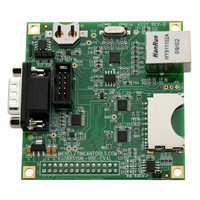
BOARD EVAL MAC/PHY FOR KSZ8851
Manufacturer
Micrel Inc
Series
LinkMD®r
Datasheets
1.KSZ8851SNL-BBE-EVAL.pdf
(80 pages)
2.KSZ8851SNL-BBE-EVAL.pdf
(3 pages)
3.KSZ8851SNL-BBE-EVAL.pdf
(1 pages)
Specifications of KSZ8851SNL-BBE-EVAL
Design Resources
BeagleBoard Zippy2
Main Purpose
Interface, Ethernet Controller (PHY and MAC)
Embedded
No
Utilized Ic / Part
KSZ8851SNL
Primary Attributes
1 Port, 100BASE-TX/10BASE-T
Secondary Attributes
SPI Interface, LinkMD Cable Diagnostics
Lead Free Status / RoHS Status
Lead free / RoHS Compliant
Other names
576-3602
KSZ8851SNL-BBE-EVL
ZIPPY2
KSZ8851SNL-BBE-EVL
ZIPPY2
Available stocks
Company
Part Number
Manufacturer
Quantity
Price
Company:

Part Number:
KSZ8851SNL-BBE-EVAL
Manufacturer:
Micrel Inc
Quantity:
135


Pin Description
August 2009
Micrel, Inc.
Pin Number
10
11
12
13
14
15
16
17
18
19
1
2
3
4
5
6
7
8
9
VDD_CO1.8
VDD_A1.8
VDD_A3.3
Pin Name
EED_IO
INTRN
DGND
AGND
AGND
AGND
EECS
EESK
RSTN
LED0
RXM
ISET
PME
TXM
RXP
TXP
Ipd/O
Type
Opu
Opu
Opu
Gnd
Opd
Gnd
Opd
Gnd
Gnd
I/O
I/O
I/O
I/O
Ipu
P
P
P
O
Pin Function
Programmable LED output to indicate PHY activity/status.
LED is ON when output is LOW; LED is OFF when output is HIGH.
LED indicators
Link (up) = LED On; Activity = LED Blink; Link/Act = LED On/Blink;
Speed = LED On (100BASE-T); LED Off (10BASE-T)
Power Management Event (default active low)
It is asserted (low or high depends on polarity set in PMECR register) when one of the
wake-on-LAN events is detected by KSZ8851SNL. The KSZ8851SNL is requesting the
system to wake up from low power mode.
Interrupt Not
An active low signal to host CPU to indicate an interrupt status bit is set. This pin needs
an external 4.7K pull-up resistor.
Digital IO ground.
1.8V regulator output . This 1.8V output pin provides power to pins 9 (VDD_A1.8) and 23
(VDD_D1.8) for core VDD supply.
If VDD_IO is set for 1.8V then this pin should be left floating, pins 9 (VDDA_1.8) and 23
(VDD_D1.8) will be sourced by the external 1.8V supply that is tied to pins 25 and 30
(VDD_IO) with appropriate filtering.
In/Out Data from/to external EEPROM
Config Mode: The pull-up/pull-down value is latched as with/without EEPROM during
power-up / reset. See “Strapping Options” section for details.
EEPROM Serial Clock
A 4μs (OBCR[1:0]=11 on-chip bus speed @ 25MHz) or 800ns (OBCR[1:0]=00 on-chip
bus speed @ 125 MHz) serial output clock to load configuration data from the serial
EEPROM.
Analog ground.
1.8V analog power supply from VDD_CO1.8 (pin 5) with appropriate filtering. If VDD_IO is
1.8V, this pin must be supplied power from the same source as pins 25 and 30 (VDD_IO)
with appropriate filtering.
EEPROM Chip Select
This signal is used to select an external EEPROM device.
Physical receive (MDI) or transmit (MDIX) signal (+ differential).
Physical receive (MDI) or transmit (MDIX) signal (– differential).
Analog ground.
Physical transmit (MDI) or receive (MDIX) signal (+ differential).
Physical transmit (MDI) or receive (MDIX) signal (– differential).
3.3V analog V
Set physical transmits output current.
Pull-down this pin with a 3.01K 1% resistor to ground.
Analog ground.
Reset Not.
LED1 (pin 32)
LED0 (pin 1)
DD
1
defined as follows:
input power supply with well decoupling capacitors.
11
Chip Global Control Register: CGCR bit [9]
100BT
LINK/ACT
0 (Default)
1
ACT
LINK
KSZ8851SNL/SNLI
M9999-083109-2.0
Related parts for KSZ8851SNL-BBE-EVAL
Image
Part Number
Description
Manufacturer
Datasheet
Request
R

Part Number:
Description:
BOARD EVALUATION KSZ8851SNL
Manufacturer:
Micrel Inc
Datasheet:

Part Number:
Description:
IC CTLR MAC/PHY NON-PCI 32-MLF
Manufacturer:
Micrel Inc
Datasheet:

Part Number:
Description:
IC CTLR MAC/PHY NON-PCI 32-QFN
Manufacturer:
Micrel Inc
Datasheet:

Part Number:
Description:
Manufacturer:
Micrel Inc
Datasheet:
Part Number:
Description:
Manufacturer:
Micrel Inc
Datasheet:
Part Number:
Description:
Manufacturer:
Micrel Inc
Datasheet:
Part Number:
Description:
Manufacturer:
Micrel Inc
Datasheet:
Part Number:
Description:
Manufacturer:
Micrel Inc
Datasheet:
Part Number:
Description:
Manufacturer:
Micrel Inc
Datasheet:
Part Number:
Description:
Manufacturer:
Micrel Inc
Datasheet:
Part Number:
Description:
Manufacturer:
Micrel Inc
Datasheet:
Part Number:
Description:
Manufacturer:
Micrel Inc
Datasheet:
Part Number:
Description:
Manufacturer:
Micrel Inc
Datasheet:
Part Number:
Description:
Manufacturer:
Micrel Inc
Datasheet: