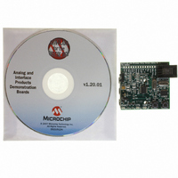
MCP2140DM-TMPSNS Microchip Technology, MCP2140DM-TMPSNS Datasheet - Page 11

MCP2140DM-TMPSNS
Manufacturer Part Number
MCP2140DM-TMPSNS
Description
BOARD DEMO FOR MCP2140
Manufacturer
Microchip Technology
Datasheets
1.MCP2140-ISO.pdf
(58 pages)
2.MCP2140-ISO.pdf
(6 pages)
3.MCP2140DM-TMPSNS.pdf
(52 pages)
Specifications of MCP2140DM-TMPSNS
Main Purpose
Interface, IrDA
Embedded
Yes, MCU, 8-Bit
Utilized Ic / Part
MCP2140
Primary Attributes
IrDA Controller with PIC18F MCU and Temp Sensor Temp
Secondary Attributes
Set up as a Data Logger
Processor To Be Evaluated
MCP2140
Interface Type
ICSP
Silicon Manufacturer
Microchip
Silicon Core Number
MCP2140
Kit Application Type
Sensing - Temperature
Application Sub Type
Temperature Sensor
Kit Contents
Board
Rohs Compliant
Yes
Lead Free Status / RoHS Status
Lead free / RoHS Compliant
Lead Free Status / RoHS Status
Lead free / RoHS Compliant, Lead free / RoHS Compliant
Other names
MCP2140DM-TMPSNSR
MCP2140DM-TMPSNSR
MCP2140DM-TMPSNSR
Available stocks
Company
Part Number
Manufacturer
Quantity
Price
Company:
Part Number:
MCP2140DM-TMPSNS
Manufacturer:
Microchip Technology
Quantity:
135
Company:
Part Number:
MCP2140DM-TMPSNS
Manufacturer:
MICROCHIP
Quantity:
12 000
2.1
2.2
2.3
2004 Microchip Technology Inc.
INTRODUCTION
FEATURES
GETTING STARTED
Chapter 2. MCP2140 IrDA Standard Wireless
The MCP2140 IrDA Standard Wireless Temperature Sensor Demo Board
demonstrates the MCP2140 device in a real-world application. In addition, the system
designer will be able to use this design as an example of how to integrate an IR port
into their system.
The MCP2140 IrDA Standard Wireless Temperature Sensor Demo Board has the
following features:
• Demo board communicates directly to Primary device (PDA or laptop computer)
• Data is transmitted in an easy-to-read format
• Reprogrammable PIC18F1320 with In-Circuit Debugger (ICD) interface for user
• Header that allows either several board signals to be monitored or allows the
• Three LEDs that indicate MCP2140 status (CTS, DSR and PHACT activity)
• Powered by three AAA batteries
• Power jumper and power LED indicator
The MCP2140 IrDA Standard Wireless Temperature Sensor Demo Board is fully assem-
bled and tested for evaluation and demonstration of the MCP2140 features. A block
diagram of the demo board is shown in Figure 2-1. Refer to Appendix A. “Schematic
and Layouts” and Appendix B. “Bill-Of-Materials (BOM)” for more detailed circuit
information.
FIGURE 2-1:
running a terminal emulation application program
application development
MCP2140 IrDA Standard Wireless Temperature Sensor Demo Board to be
interfaced to user’s system
(for programming)
Temperature Sensor Demo Board
ICD Header
J1
1.5V Batteries
Three AAA
WIRELESS TEMPERATURE SENSOR
3
S2
MCP2140 DEMO BOARD BLOCK DIAGRAM
U11
U1
TC1047A
System
Power
DEMO BOARD USER’S GUIDE
MCP2140 IrDA
RESET
Temp
Sensor
LEDs
7
Power
DSR
CTS
PHACT
2
Control/Status
UART
Standard Controller
MCP2140
U2
IrDA
®
STANDARD
®
TXIR
RXIR
Transceiver
DS51487A-page 7
Optical


