MCP2140DM-TMPSNS Microchip Technology, MCP2140DM-TMPSNS Datasheet - Page 14
MCP2140DM-TMPSNS
Manufacturer Part Number
MCP2140DM-TMPSNS
Description
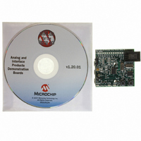
BOARD DEMO FOR MCP2140
Manufacturer
Microchip Technology
Datasheets
1.MCP2140-ISO.pdf
(58 pages)
2.MCP2140-ISO.pdf
(6 pages)
3.MCP2140DM-TMPSNS.pdf
(52 pages)
Specifications of MCP2140DM-TMPSNS
Main Purpose
Interface, IrDA
Embedded
Yes, MCU, 8-Bit
Utilized Ic / Part
MCP2140
Primary Attributes
IrDA Controller with PIC18F MCU and Temp Sensor Temp
Secondary Attributes
Set up as a Data Logger
Processor To Be Evaluated
MCP2140
Interface Type
ICSP
Silicon Manufacturer
Microchip
Silicon Core Number
MCP2140
Kit Application Type
Sensing - Temperature
Application Sub Type
Temperature Sensor
Kit Contents
Board
Rohs Compliant
Yes
Lead Free Status / RoHS Status
Lead free / RoHS Compliant
Lead Free Status / RoHS Status
Lead free / RoHS Compliant, Lead free / RoHS Compliant
Other names
MCP2140DM-TMPSNSR
MCP2140DM-TMPSNSR
MCP2140DM-TMPSNSR
Available stocks
Company
Part Number
Manufacturer
Quantity
Price
Company:

Part Number:
MCP2140DM-TMPSNS
Manufacturer:
Microchip Technology
Quantity:
135
Company:
Part Number:
MCP2140DM-TMPSNS
Manufacturer:
MICROCHIP
Quantity:
12 000


MCP2140 IrDA
DS51487A-page 10
2.3.2
There are two programs that can be demonstrated on the demo board. These are:
• The transmission of a 250 byte data string from a table in the PIC18F1320 to the
• The transmission of the “temperature” reading of the TC1047A to the Primary
Typical Primary devices include Palm or Pocket PC PDAs and Laptop PCs with an IrDA
standard infrared port.
The PIC18F1320 source code for the MCP2140 IrDA Standard Wireless Temperature
Sensor Demo Board is available for download from the Microchip web site at
www.microchip.com.
2.3.2.1
This program will be selected when the RESET switch is depressed and then released
(with the S2 switch not pressed). The PIC18F1320 will initialize the system and wait to
receive a data byte. Once a data byte is received, the PIC18F1320 will transmit a
250-byte table from memory to the MCP2140.
The PIC18F1320 follows the flow control of the MCP2140 to ensure that data is not lost.
The MCP2140 handles all the IrCOMM protocol for the data packets that it receives
from the PIC18F1320.
Once the table has completed transmission, the PIC18F1320 will wait to receive the
next character that will cause the 250-byte table to be transmitted (again).
The 250-byte data table transmitted from the MCP2140 IrDA Standard Wireless Temper-
ature Sensor Demo Board to the Primary device is shown in Appendix D. “MCP2140
250 Byte Data Transmit Table”. These values will be displayed in the Primary device’s
Terminal Emulation program window.
2.3.2.2
This program will be selected when both the RESET and S2 switches are depressed,
the RESET switch is released and the S2 switch is held momentarily. The PIC18F1320
will initialize the system and wait to receive a data byte. Once a data byte is received,
the PIC18F1320 will continuously transmit the following string:
The PIC18F1320 follows the flow control of the MCP2140 to ensure that data is not lost.
The “measured” temperature will vary as a result of the system voltage of the demo
board. This is due to the PIC18F1320 being powered directly from the AAA batteries
and the A/D module using V
The current firmware implementation will transmit a larger value to the Primary device
as the battery voltage decreases, given a constant temperature.
A firmware technique to correct for this would be to use the PIC18F1320 LVD module.
A hardware technique would be to use a voltage regulator to ensure that the system
voltage remains constant, regardless of the voltage output of the batteries.
®
Primary device.
device.
Standard Wireless Temp Sensor Demo Board
“Temp = xx” to the MCP2140, approximately once per second, where xx is the
temperature in °C.
The Embedded System Firmware
“TRANSMIT 250 BYTE DATA STRING” PROGRAM DESCRIPTION
“TRANSMIT TEMPERATURE” PROGRAM DESCRIPTION
DD
as its reference voltage.
2004 Microchip Technology Inc.
Related parts for MCP2140DM-TMPSNS
Image
Part Number
Description
Manufacturer
Datasheet
Request
R

Part Number:
Description:
IC IRDA CONTROLLR DTE/DCE 18SOIC
Manufacturer:
Microchip Technology
Datasheet:

Part Number:
Description:
The MCP2140 Embeds Irda Protocol Handling And Bit Encoding/decoding, And Provides The Lowest Cost, Lowest Power Consumption Solution For Adding Irda Connectivity to Embedded Systems
Manufacturer:
Microchip Technology, Inc.
Datasheet:

Part Number:
Description:
IC IRDA CONTROLLER DTE/DCE 18DIP
Manufacturer:
Microchip Technology
Datasheet:

Part Number:
Description:
IC IRDA CONTROLLR DTE/DCE 20SSOP
Manufacturer:
Microchip Technology
Datasheet:

Part Number:
Description:
9600 BAUD FIXED SPEED IRDA PROTOCOL HANDLER & BIT ENCODER/DECODER, -40C to +85C, 20-SSOP 208mil, TUBE
Manufacturer:
Microchip Technology
Datasheet:
Part Number:
Description:
IrDA� Standard Protocol Stack Controller With Fixed 9600 Baud Communication Rate
Manufacturer:
MICROCHIP [Microchip Technology]
Datasheet:

Part Number:
Description:
Manufacturer:
Microchip Technology Inc.
Datasheet:
Part Number:
Description:
Manufacturer:
Microchip Technology Inc.
Datasheet:
Part Number:
Description:
Manufacturer:
Microchip Technology Inc.
Datasheet:
Part Number:
Description:
Manufacturer:
Microchip Technology Inc.
Datasheet:
Part Number:
Description:
Manufacturer:
Microchip Technology Inc.
Datasheet:
Part Number:
Description:
Manufacturer:
Microchip Technology Inc.
Datasheet: